Download
1 / 36
440 likes | 1.2k Views
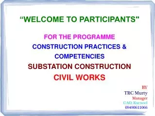
“WELCOME TO PARTICIPANTS" FOR THE PROGRAMME CONSTRUCTION PRACTICES & COMPETENCIES SUBSTATION CONSTRUCTION CIVIL WORKS BY TRC Murty Manager CAO, Kurnool 09490611066. 1. Identification of Permanent Bench Mark/s.

E N D
“WELCOME TO PARTICIPANTS" • FOR THE PROGRAMME • CONSTRUCTION PRACTICES & • COMPETENCIES • SUBSTATION CONSTRUCTION • CIVIL WORKS • BY • TRC Murty • Manager • CAO, Kurnool • 09490611066
1. Identification of Permanent Bench Mark/s. 2. Transfer of RLs from Bench mark/s to SS site and counter checking of RL accuracy by traversing in two different routes. 3. Fixing of base line/reference line. 4. Traversing by Theodalite/Total Station. 5. Marking of Grids & fixing of grid pillars. Construction of SubstationSurveying
6. Construction of Bench mark pillars & transfer of RLs. 7. Fixation of Boundaries as shown by Revenue authorities. 8. Field marking of soil testing locations like Trial pits, boreholes, Plate load tests, etc. 9. Preparation contour map from data of Total station. 10. Fixing of formation level. Construction of SubstationSurveying
SITE SELECTION: SUB STATION CONSTRUCTIONLAND & INFRASTRUCTURE
Approval of Testing Lab: 1. Identification/visiting of Institution having adequate test facilities/proposed by execution agency to ascertain the testing facilities/capability. Calibration of testing equipments shall also be ensured. 2. Proposal for approval of Testing Labs/Institutions (preferably Govt. Institutions). Pvt. Institutions may also be considered based on the availability of infrastructure and if Govt. Institutions are not available in the vicinity. 3. Approval of Testing Labs/Institutions from competent authority (CAO i/c) & communication to execution agency. Construction of Substation
Source approval for Coarse & Fine aggregates: 1. Identification of Mining area, crusher/supply agency for coarse aggregates. 2. Identification of River mining area for fine aggregates. 3. Collection of samples & testing at approved lab. 4. Interpretation of results and limits w.r.t. relevant Standards/specifications. 5. Approval of sources from competent authority (CAO i/c) & communication to execution agency. Construction of Substation
1. Sieve analysis / Gradation – As per IS 383 IS Sieve Designation Percentage passing for graded aggregate of nominal size 40mm 20mm 16 mm 12.5 mm 63 mm - - - - 40 mm 95 to 100 100 - - 20 mm 30 to 70 95 to 100 100 100 16 mm - - 90 to100 - 12.5 mm - - - 90 to 100 10 mm 10 to 35 25 to 55 30 to 70 40 to 85 4.75 mm 0 to 5 0 to 10 0 to 10 0 to 10 2.36 mm - - - - b. Flakiness Index Not to Exceed 25% c. Crushing value Not to exceed 45% d. Presence of delterious material Not to exceed 5% e. Hardness : For road work Abrasion value not more than 40% Impact value not more than 40% Construction of SubstationAcceptance criteria & Permissible limits for Coarse aggregates
Construction of SubstationAcceptance criteria & Permissible limits for Fine aggregates
Bulking of sand: Construction of Substation
Excavation : 1. Safety is utmost. 2. Marking of pits of required size as per G.A.& Foundation drg. with reference to base/grid lines. Construction of marking pillars. 3. Stacking of excavated soil beyond the pit (min 1m. away from pit edge). 4. Excavation of the pits by mechanical means shall be carried up to 300mm less than the required level. 300mm depth excavation to reach required level shall be carried by manually to avoid any disturbance in founding strata. 5. Excavation beyond required/desired foundation level shall be brought to required level by filling with PCC or sand filling. 6. Provision of shoring & shuttering for clayey soils/where there is a chance of sliding of pit sides. 7. Checking of depth with reference to local B.M. & base evenness. 8. Clearance for PCC/bed concrete. Construction of Substation
¼ D ¼ D 0.5m 0.5m 2m D EXCAVATION in Sandy / Silty & Filled up soils Slopped Excavation Stepped Excavation GENERALLY FOR STABILITY OF THE PIT AT LEAST 1:4 SLOPE SHALL BE MAINTAINED. FOR WBC, LOOSE, SOFT OR SLUSHY SOILS, THE INCLINATION OF SLOPE SHALL BE INCREASED. GENERALLY FOR EVERY 2M DEPTH THE WIDTH OF THE STEP CUTTING SHALL BE 0.5M. FOR LOOSE WBC, SOFT OR SLUSHY SOILS WIDTH OF STEP SHALL BE SUITABLY INCREASED
Excavation in rock : 1. Excavation in hard rock, blasting can be resorted to. 2. Reference shall be made to statutory rules for blasting and use of explosives. 3. No blasting is permitted near permanent works or dwelling areas. 4. Blasting shall be so made that pits are excavated as nearer to the desired dimensions as practicable. 5. The work of blasting in rock is carried out in three separate operations: a) Drilling of holes to hold explosives charge. b) Charging of the drilled holes. c) Firing of charge. Construction of Substation
Concrete: 1. Concrete mixing can be by: a) Volume batching / Measurement. b) Mix design. 2. Grade of concrete generally used are: a) Lean concrete, M5 (1:4:8), M10 (1:3:6) b) Normal concrete, M15 (1:2:4), M20 (1:1½:3) 3. The measuring box of size 35x25x40cm. - 0. 035 cum. = 1 bag of cement 4. Water Cement Ratio shall be between 0.5 to 0.6 5. Workability shall be checked by Slump test. a) Desirable slump for beams & slabs is 50 to 100mm. b) Columns – 75 to 100 mm. c) Road work – 20 to 28mm. Construction of Substation
Concreting : 1. Ensure base surface cleanliness. 2. Check for quality & availability of requisite material i.e. Cement, aggregates, water, etc., prior to start of work. 3. Check the working condition of concrete mixers, vibrators/compactors, etc. 4. Mixing of concrete in specified mix with mechanical concrete mixer. 5. Placement of concrete in required thickness and its compaction. 6. Check for surface level of concrete. 7. Ensure curing for min 10 days after 24 hours completion of concrete work. Construction of Substation
Curing & Strength Relationship 160 A 140 D 120 C 100 COMPRESSIVE STRENGTH % of 28 day strength of Moist cured Concrete 80 B 60 40 20 0 4 7 1 2 3 5 6 8 9 10 11 12 AGE (Months) A - Continuously moist cured.B - Continuously air cured. C - Moist cured 1 month then air cured.D - Moist cured 3 months then air cured.
Concrete mix: 1. Nominal mix – by volume (1:2:4), (1:1:2), etc. 2. Design mix – by weight M20, M25, M30, etc., grades Construction of Substation
Reinforced Cement Concrete (RCC) : 1. Preparation of bar bending schedule as per constrn. drg. 2. Inspection of steel quality – Approved manufacturer/vendor, size (dia & length), test reports, free from rust/soil/grease/oil, etc. 3. Fixing of bars in specified spacing with binding wire/tack welding, providing of cover blocks for maintaining clear cover of concrete. 4. Fixing of form boxes and checking for dimensional correctness. Construction of Substation
Reinforced Cement Concrete (RCC) : 5. Placing of concrete of specified grade and compaction at regular intervals with vibrator/pocking rod. 5. Slump test and collection of cubes for testing as per FQP. 6. Fixing of foundation/anchor bolts of respective equipment structure using foundation bolt template by maintaining true level. 7. Cleaning of bolts immediately after completion of concreting. Removal of bolt template on setting of concrete and & apply grease to bolts. 8. Curing for min 10 days. Construction of Substation
Reinforcement steel: 1. Minimum lap length in Tension – 30 d 2. Minimum lap length in compression – 24 d 3. Minimum bond length in Tension – 58 d 4. Minimum bond length in Compression – 47 d Where 'd' is the diameter of reinforcement bar Construction of Substation
Back filling : 1. Removal of form work after 24 hrs of completion of CC/RCC work, check for honeycombing/defects, repair the same with rich mix. 2. Back filling of pits with excavated soil/borrowed earth if the excavated soil is not fit for filling in layers of 200mm thick each. 3. Compaction of filled up soil with watering & ramming each layer. 4. Collection of requisite samples of compacted soil for testing its compactness. 5. Clearance for erection of structure. Construction of Substation
Roads : Two types for our references as far as Specifications are concerned viz., 1. WBM Roads with Black topping. 2. Concrete Roads. Construction of Substation
WBM (Water Bound Mc’adam) comprises of (i) Sub base course made with 90-45 mm sizes broken metal mixed with 13.2 mm sized screening & binding material for 200 mm thick layer laid in 2 layers over the compacted subgrade. (ii) Base course comprising of 2 layers of 75 mm thick each made of 63-45 mm sized metal mixed with 11.2 mm sizes screening and binding material . Black topping is done with 25 mm thick bituminous carpeting comprising of bitumen & screening material. Seal coat is optional. 460 mm brick on edge on both side on shoulders. Drains as per requirement. Construction of Substation
CONCRETE ROADS (i) Comprises of 100 mm thick layer of 1:4:8 PCC over which 100mm thick RCC is laid in prop 1:2:4 with 8 Dia bars @ 300mm c/s both ways (optional). (ii) Expansion joints are provided at interval of 3.75 m. Expansion joints are 25mm wide and are filled with expansion jointing filler materials. (iii) From width point of view single lane roads are 3.75 m and double lane are 7.0 m (IRC). POWERGRID specification 3.75 m and 5.5 m. Construction of Substation
6000 4670 3750 115 MM THK BRICK SOLING 25MM THK PRE MIX CARPET 75MM THK WBM WITH 63-45MM SIZE METAL 460 460 (2 BRICKS) 2 BRICKS 25 MM THK MOORUM LAYER 75MM THK WBM BASE COURSE WITH 63-45MM SIZE METAL 25MM THK MOORUM LAYER 200MM THK WBM SUB-BASE WITH 90-45 MM SIZE METAL ROADS IN SUBSTATIONS CROSS-SECTION OF TOWNSHIP ROAD
Construction of Roads: 1. Marking of roads as per General Arrangement drawing of SS. 2. Cutting/embankment subsoil as per designed RL. 3. Identification of source of materials like crushed stones, aggregates, binding material, bitumen, etc., testing and its approval. 4. Transportation & stacking of material at site. 5. Spreading, watering & rolling of various layers of sub base. 6. Check for compactness of sub base. 7. Black topping with macadam & 8. Check for proper camber. 9. Rolling & check for compacted thickness. 10. Berms development.` Construction of Substation
Construction of Substation • Drains: • Normally for discharge of Rain /Strom water disposal • We have 3 types: • (i) Conduting system (Hume pipes/RCC Pipes) • (ii) Trapezoidal/ Rectangular brick/concrete lined. • (iii) Open Kucha drain
DRAINS IN SUBSTATIONS CROSS-SECTION OF STORM WATER DRAIN – TYPE A
DRAINS IN SUBSTATIONS CROSS-SECTION OF STORM WATER DRAIN – TYPE B
Construction Drains: 1. Marking of drains as per General Arrangement drawing of SS. 2. Observe the natural gradient of Ground for locating the discharge point. It is advisable to connect the storm drain to rain harvesting pond/pit individually depending upon the formation level of ground. 3. Excavation of trench with required gradient & width. 4. Making of gradient blocks. 5. Laying of PCC. 6. Construction of walls with RR/Brick Masonry or with RCC. 7. Coping with CC 1:2:4 for RR/Brick masonry. 8. Putting pre-cast RCC cover slabs as per requirement. 9. Construction of culverts at crossings. Construction of Substation
Construction of Substation • Equipment Foundations:- • Transformers, Reactor plinths. • Support structures lattice or pipe for CBs, Isolators, LA, CTs, CVTs, Wave Traps, Marshalling Kiosks. • Lightning Masts, Gantries Towers. • Rigid type Bus-bar supports.
Construction of Substation • Other Civil works: • Cable trenches. • Anti-weed treatment & Metal spreading. • Fencing around switch yard. • Roads and drains. • Railway track or road cum rail track.
Equipment Foundation a x a 4a 4 + B B 3 3a 3a 300 FGL 3 3 3a 3a 3 SECTION A-A H a D E 75 D a A x A 75 75 VIEW B-B ELEVATION FGL A A B 3a 3 + ‘4’ & ‘4a’ AS PER SECTION A-A 2 1 SECTIONAL ELEVATION
Construction of Substation • Safety during construction: • 1. Creation of safety awareness in all workers/staff. • 2. Barricading the work area with safety ribbon/flags, etc. • 3. Using P.P.Es. • 4. Use of safety ladders for getting in the pits & for climbing heights. • 5. Proper earthing of working equipment while working in charged area. • 6. Conducting of mock drills & safety awareness program on regular basis. • 7. Ensure availability of vehicle at all time during work. • 8. Deployment of workers as per their skill.
Construction of Substation • THANK YOU • By • TRC Murty • Manager • CAO, Kurnool • 09490611066