Chapter 4 Network Layer
Chapter 4 Network Layer. Computer Networking: A Top Down Approach 6 th edition Jim Kurose, Keith Ross Addison-Wesley March 2012. Chapter 4: network layer. chapter goals: understand principles behind network layer services: network layer service models forwarding versus routing


Chapter 4 Network Layer
E N D
Presentation Transcript
Chapter 4Network Layer Computer Networking: A Top Down Approach 6th edition Jim Kurose, Keith RossAddison-WesleyMarch 2012 Network Layer
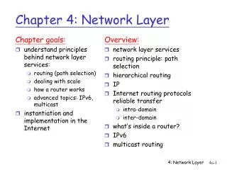
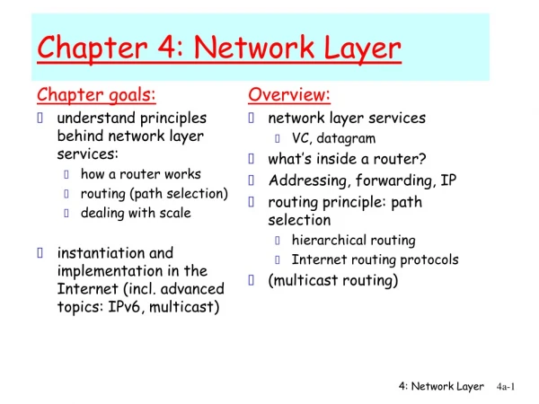
Chapter 4: network layer chapter goals: • understand principles behind network layer services: • network layer service models • forwarding versus routing • how a router works • routing (path selection) • broadcast, multicast • instantiation, implementation in the Internet Network Layer
Host, router network layer functions: ICMP protocol • error reporting • router “signaling” IP protocol • addressing conventions • datagram format • packet handling conventions Routing protocols • path selection • RIP, OSPF, BGP forwarding table Recall Layering: The Internet Network layer Transport layer: TCP, UDP Network layer Link layer physical layer Network Layer
4.1 introduction 4.2 virtual circuit and datagram networks 4.3 what’s inside a router 4.4 IP: Internet Protocol datagram format IPv4 addressing ICMP IPv6 4.5 routing algorithms link state distance vector hierarchical routing 4.6 routing in the Internet RIP OSPF BGP 4.7 broadcast and multicast routing Chapter 4: outline Network Layer
transport segment from sending to receiving host on sending side encapsulates segments into datagrams on receiving side, delivers segments to transport layer network layer protocols in everyhost, router router examines header fields in all IP datagrams passing through it network data link physical network data link physical network data link physical network data link physical network data link physical network data link physical network data link physical network data link physical network data link physical network data link physical network data link physical application transport network data link physical application transport network data link physical Network layer Network Layer
Two key network-layer functions analogy: • routing: process of planning trip from source to dest • forwarding: process of getting through single interchange • forwarding: move packets from router’s input to appropriate router output • routing: determine route taken by packets from source to dest. • routing algorithms Network Layer
routing algorithm local forwarding table header value output link routing algorithm determines end-end-path through network forwarding table determines local forwarding at this router 0100 0101 0111 1001 3 2 2 1 value in arriving packet’s header 1 0111 2 3 Interplay between routing and forwarding Network Layer
Connection setup • 3rd important function in some network architectures: • ATM, frame relay, X.25 • before datagrams flow, two end hosts and intervening routers establish virtual connection • routers get involved • network vs transport layer connection service: • network: between two hosts (may also involve intervening routers in case of VCs) • transport: between two processes Network Layer
example services for individual datagrams: guaranteed delivery guaranteed delivery with less than 40 msec delay example services for a flow of datagrams: in-order datagram delivery guaranteed minimum bandwidth to flow restrictions on changes in inter-packet spacing Network service model Q: What service model for “channel” transporting datagrams from sender to receiver? Network Layer
Network layer service models: Guarantees ? Network Architecture Internet ATM ATM ATM ATM Service Model best effort CBR VBR ABR UBR Congestion feedback no (inferred via loss) no congestion no congestion yes no Bandwidth none constant rate guaranteed rate guaranteed minimum none Loss no yes yes no no Order no yes yes yes yes Timing no yes yes no no Network Layer
4.1 introduction 4.2 virtual circuit and datagram networks 4.3 what’s inside a router 4.4 IP: Internet Protocol datagram format IPv4 addressing ICMP IPv6 4.5 routing algorithms link state distance vector hierarchical routing 4.6 routing in the Internet RIP OSPF BGP 4.7 broadcast and multicast routing Chapter 4: outline Network Layer
Connection, connection-less service • datagram network provides network-layer connectionless service • virtual-circuit network provides network-layer connection service • analogous to TCP/UDP connecton-oriented / connectionless transport-layer services, but: • service:host-to-host • no choice:network provides one or the other • implementation:in network core Network Layer
no call setup at network layer routers: no state about end-to-end connections no network-level concept of “connection” packets forwarded using destination host address application transport network data link physical application transport network data link physical Datagram networks 1. send datagrams 2. receive datagrams Network Layer
4 billion IP addresses, so rather than list individual destination address list range of addresses (aggregate table entries) 1 3 2 Datagram forwarding table routing algorithm local forwarding table dest address output link address-range 1 address-range 2 address-range 3 address-range 4 3 2 2 1 IP destination address in arriving packet’s header Network Layer
used to setup, maintain teardown VC used in ATM, frame-relay, X.25 not used in today’s Internet application transport network data link physical application transport network data link physical Virtual circuits: signaling protocols 6. receive data 5. data flow begins 4. call connected 3. accept call 1. initiate call 2. incoming call Network Layer
Datagram forwarding table Destination Address Range 11001000 00010111 00010000 00000000 through 11001000 00010111 00010111 11111111 11001000 00010111 00011000 00000000 through 11001000 00010111 00011000 11111111 11001000 00010111 00011001 00000000 through 11001000 00010111 00011111 11111111 otherwise Link Interface 0 1 2 3 Q: but what happens if ranges don’t divide up so nicely? Network Layer
Longest prefix matching longest prefix matching when looking for forwarding table entry for given destination address, use longest address prefix that matches destination address. Link interface 0 1 2 3 Destination Address Range 11001000 00010111 00010*** ********* 11001000 00010111 00011000 ********* 11001000 00010111 00011*** ********* otherwise examples: which interface? DA: 11001000 00010111 00010110 10100001 which interface? DA: 11001000 00010111 00011000 10101010 Network Layer
Internet (datagram) data exchange among computers “elastic” service, no strict timing req. many link types different characteristics uniform service difficult “smart” end systems (computers) can adapt, perform control, error recovery simple inside network, complexity at “edge” ATM (VC) evolved from telephony human conversation: strict timing, reliability requirements need for guaranteed service “dumb” end systems telephones complexity inside network Datagram or VC network: why? Network Layer
4.1 introduction 4.2 virtual circuit and datagram networks 4.3 what’s inside a router 4.4 IP: Internet Protocol datagram format IPv4 addressing ICMP IPv6 4.5 routing algorithms link state distance vector hierarchical routing 4.6 routing in the Internet RIP OSPF BGP 4.7 broadcast and multicast routing Chapter 4: outline Network Layer
host, router network layer functions: • IP protocol • addressing conventions • datagram format • packet handling conventions forwarding table The Internet network layer transport layer: TCP, UDP • routing protocols • path selection • RIP, OSPF, BGP network layer • ICMP protocol • error reporting • router “signaling” link layer physical layer Network Layer
IP protocol version number 32 bits total datagram length (bytes) header length (bytes) type of service head. len ver length for fragmentation/ reassembly fragment offset “type” of data flgs 16-bit identifier max number remaining hops (decremented at each router) upper layer time to live header checksum 32 bit source IP address 32 bit destination IP address upper layer protocol to deliver payload to e.g. timestamp, record route taken, specify list of routers to visit. options (if any) data (variable length, typically a TCP or UDP segment) IP datagram format how much overhead? • 20 bytes of TCP • 20 bytes of IP • = 40 bytes + app layer overhead Network Layer
network links have MTU (max.transfer size) - largest possible link-level frame different link types, different MTUs large IP datagram divided (“fragmented”) within net one datagram becomes several datagrams “reassembled” only at final destination IP header bits used to identify, order related fragments … … reassembly IP fragmentation, reassembly fragmentation: in: one large datagram out: 3 smaller datagrams Network Layer
length =1500 length =1500 length =4000 length =1040 ID =x ID =x ID =x ID =x fragflag =0 fragflag =1 fragflag =1 fragflag =0 offset =0 offset =0 offset =370 offset =185 one large datagram becomes several smaller datagrams IP fragmentation, reassembly example: • 4000 byte datagram • MTU = 1500 bytes 1480 bytes in data field offset = 1480/8 Network Layer
4.1 introduction 4.2 virtual circuit and datagram networks 4.3 what’s inside a router 4.4 IP: Internet Protocol datagram format IPv4 addressing ICMP IPv6 4.5 routing algorithms link state distance vector hierarchical routing 4.6 routing in the Internet RIP OSPF BGP 4.7 broadcast and multicast routing Chapter 4: outline Network Layer
IP address: 32-bit identifier for host, router interface interface: connection between host/router and physical link router’s typically have multiple interfaces host typically has one or two interfaces (e.g., wired Ethernet, wireless 802.11) IP addresses associated with each interface 223.1.1.2 223.1.3.27 IP addressing: introduction 223.1.1.1 223.1.2.1 223.1.1.4 223.1.2.9 223.1.1.3 223.1.2.2 223.1.3.2 223.1.3.1 223.1.1.1 = 11011111 00000001 00000001 00000001 223 1 1 1 Network Layer
Classful Addressing (historical) Network Layer
Q: how are interfaces actually connected? A: we’ll learn about that in chapter 5, 6. 223.1.1.2 223.1.3.27 IP addressing: introduction 223.1.1.1 223.1.2.1 223.1.1.4 223.1.2.9 223.1.1.3 223.1.2.2 A: wired Ethernet interfaces connected by Ethernet switches 223.1.3.2 223.1.3.1 For now: don’t need to worry about how one interface is connected to another (with no intervening router) A: wireless WiFi interfaces connected by WiFi base station Network Layer
IP address: subnet part - high order bits host part - low order bits what’s a subnet ? device interfaces with same subnet part of IP address can physically reach each other without intervening router subnet Subnets 223.1.1.1 223.1.2.1 223.1.1.2 223.1.1.4 223.1.2.9 223.1.2.2 223.1.3.27 223.1.1.3 223.1.3.2 223.1.3.1 network consisting of 3 subnets Network Layer
recipe to determine the subnets, detach each interface from its host or router, creating islands of isolated networks each isolated network is called a subnet 223.1.1.0/24 223.1.2.0/24 223.1.1.1 223.1.2.1 223.1.1.2 223.1.1.4 223.1.2.9 223.1.2.2 223.1.3.27 223.1.1.3 223.1.3.2 223.1.3.1 223.1.3.0/24 subnet Subnets subnet mask: /24 Network Layer
how many? Subnets 223.1.1.2 223.1.1.1 223.1.1.4 223.1.1.3 223.1.7.0 223.1.9.2 223.1.9.1 223.1.7.1 223.1.8.1 223.1.8.0 223.1.2.6 223.1.3.27 223.1.2.1 223.1.2.2 223.1.3.1 223.1.3.2 Network Layer
IP addressing: CIDR CIDR:Classless InterDomain Routing • subnet portion of address of arbitrary length • address format: a.b.c.d/x, where x is # bits in subnet portion of address host part subnet part 11001000 00010111 00010000 00000000 200.23.16.0/23 Network Layer
Subnetting/Netmask • process of subnetting involves separation of network and subnet portion of an address from host identifier. • performed by a bitwise AND operation between the IP address and the subnet prefix or bit mask. • result yields the network address, and the remainder is the host identifier. following example is based on IPv4 networking. The operation may be visualized in a table using binary address formats. Network Layer
Subnetting / Netmask Another example: • Consider the IP address 192.168.40.3 that is part of Class C network 192.168.40.0. • A subnet or sub-network is defined through a network mask boundary using the specified number of significant bits as 1s. • Since Class C defines networks with a 24-bit boundary, we can then consider that the most significant 24 bits are 1s, and the lower 8 bits are 0s. • This translates to the dotted decimal notation 255.255.255.0, which is also compactly written as “/24” to indicate how many most significant bits are 1s. • bit-wise logical “AND” operation between host address and netmask to obtain the Class C network address as shown below: 11000000 10101000 00101000 00000011 → 192.168.40.3 11111111 11111111 11111111 00000000 → netmask (/24) 11000000 10101000 00101000 00000000 → 192.168.40.0 Network Layer
Subnetting/Netmask Another example (coont.): • Now consider that we want to change the netmask explicitly to /21 to identify a network larger than a 24-bit subnet boundary. If we now do the bit-wise operation • 11000000 10101000 00101000 00000011 → 192.168.40.3 • 11111111 11111111 11111000 00000000 → netmask (/21) • 11000000 10101000 00101000 00000000 → 192.168.40.0 • note that the network address is again 192.168.40.0. However, in the latter case, the network boundary is 21 bits. Thus, to be able to clearly distinguish between the first and the second one, it is necessary to explicitly mention the netmask. • commonly written for second example as 192.168.40.0/21, where first part is the netid and the second part is the mask boundary indicator. Network Layer
IP addresses: how to get one? Q: How does a host get IP address? • hard-coded by system admin in a file • Windows: control-panel->network->configuration->tcp/ip->properties • UNIX: /etc/rc.config • DHCP:Dynamic Host Configuration Protocol: dynamically get address from as server • “plug-and-play” Network Layer
DHCP: Dynamic Host Configuration Protocol goal: allow host to dynamically obtain its IP address from network server when it joins network • can renew its lease on address in use • allows reuse of addresses (only hold address while connected/“on”) • support for mobile users who want to join network (more shortly) DHCP overview: • host broadcasts “DHCP discover” msg [optional] • DHCP server responds with “DHCP offer” msg [optional] • host requests IP address: “DHCP request” msg • DHCP server sends address: “DHCP ack” msg Network Layer
DHCP client-server scenario DHCP server 223.1.1.0/24 223.1.2.1 223.1.1.1 223.1.1.2 arriving DHCP client needs address in this network 223.1.1.4 223.1.2.9 223.1.2.2 223.1.3.27 223.1.1.3 223.1.2.0/24 223.1.3.2 223.1.3.1 223.1.3.0/24 Network Layer
DHCP discover src : 0.0.0.0, 68 dest.: 255.255.255.255,67 yiaddr: 0.0.0.0 transaction ID: 654 DHCP client-server scenario DHCP server: 223.1.2.5 arriving client DHCP offer src: 223.1.2.5, 67 dest: 255.255.255.255, 68 yiaddrr: 223.1.2.4 transaction ID: 654 lifetime: 3600 secs DHCP request src: 0.0.0.0, 68 dest:: 255.255.255.255, 67 yiaddrr: 223.1.2.4 transaction ID: 655 lifetime: 3600 secs DHCP ACK src: 223.1.2.5, 67 dest: 255.255.255.255, 68 yiaddrr: 223.1.2.4 transaction ID: 655 lifetime: 3600 secs Network Layer
DHCP: more than IP addresses DHCP can return more than just allocated IP address on subnet: • address of first-hop router for client • name and IP address of DNS sever • network mask (indicating network versus host portion of address) Network Layer
DHCP UDP IP Eth Phy DHCP UDP IP Eth Phy DHCP DHCP DHCP DHCP DHCP DHCP DHCP DHCP DHCP DHCP DHCP: example • connecting laptop needs its IP address, addr of first-hop router, addr of DNS server: use DHCP • DHCP request encapsulated in UDP, encapsulated in IP, encapsulated in 802.1 Ethernet 168.1.1.1 • Ethernet frame broadcast (dest: FFFFFFFFFFFF) on LAN, received at router running DHCP server router with DHCP server built into router • Ethernet demuxed to IP demuxed, UDP demuxed to DHCP Network Layer
DHCP UDP IP Eth Phy DHCP UDP IP Eth Phy DHCP DHCP DHCP DHCP DHCP DHCP DHCP DHCP DHCP DHCP: example • DCP server formulates DHCP ACK containing client’s IP address, IP address of first-hop router for client, name & IP address of DNS server • encapsulation of DHCP server, frame forwarded to client, demuxing up to DHCP at client router with DHCP server built into router • client now knows its IP address, name and IP address of DSN server, IP address of its first-hop router Network Layer
DHCP: Wireshark output (home LAN) reply Message type: Boot Reply (2) Hardware type: Ethernet Hardware address length: 6 Hops: 0 Transaction ID: 0x6b3a11b7 Seconds elapsed: 0 Bootp flags: 0x0000 (Unicast) Client IP address: 192.168.1.101 (192.168.1.101) Your (client) IP address: 0.0.0.0 (0.0.0.0) Next server IP address: 192.168.1.1 (192.168.1.1) Relay agent IP address: 0.0.0.0 (0.0.0.0) Client MAC address: Wistron_23:68:8a (00:16:d3:23:68:8a) Server host name not given Boot file name not given Magic cookie: (OK) Option: (t=53,l=1) DHCP Message Type = DHCP ACK Option: (t=54,l=4) Server Identifier = 192.168.1.1 Option: (t=1,l=4) Subnet Mask = 255.255.255.0 Option: (t=3,l=4) Router = 192.168.1.1 Option: (6) Domain Name Server Length: 12; Value: 445747E2445749F244574092; IP Address: 68.87.71.226; IP Address: 68.87.73.242; IP Address: 68.87.64.146 Option: (t=15,l=20) Domain Name = "hsd1.ma.comcast.net." Message type: Boot Request (1) Hardware type: Ethernet Hardware address length: 6 Hops: 0 Transaction ID: 0x6b3a11b7 Seconds elapsed: 0 Bootp flags: 0x0000 (Unicast) Client IP address: 0.0.0.0 (0.0.0.0) Your (client) IP address: 0.0.0.0 (0.0.0.0) Next server IP address: 0.0.0.0 (0.0.0.0) Relay agent IP address: 0.0.0.0 (0.0.0.0) Client MAC address: Wistron_23:68:8a (00:16:d3:23:68:8a) Server host name not given Boot file name not given Magic cookie: (OK) Option: (t=53,l=1) DHCP Message Type = DHCP Request Option: (61) Client identifier Length: 7; Value: 010016D323688A; Hardware type: Ethernet Client MAC address: Wistron_23:68:8a (00:16:d3:23:68:8a) Option: (t=50,l=4) Requested IP Address = 192.168.1.101 Option: (t=12,l=5) Host Name = "nomad" Option: (55) Parameter Request List Length: 11; Value: 010F03062C2E2F1F21F92B 1 = Subnet Mask; 15 = Domain Name 3 = Router; 6 = Domain Name Server 44 = NetBIOS over TCP/IP Name Server …… request Network Layer
IP addresses: how to get one? Q: how does network get subnet part of IP addr? A: gets allocated portion of its provider ISP’s address space ISP's block 11001000 00010111 00010000 00000000 200.23.16.0/20 Organization 0 11001000 00010111 00010000 00000000 200.23.16.0/23 Organization 1 11001000 00010111 00010010 00000000 200.23.18.0/23 Organization 2 11001000 00010111 00010100 00000000 200.23.20.0/23 ... ….. …. …. Organization 7 11001000 00010111 00011110 00000000 200.23.30.0/23 Network Layer
200.23.16.0/23 200.23.18.0/23 200.23.30.0/23 200.23.20.0/23 . . . . . . Hierarchical addressing: route aggregation hierarchical addressing allows efficient advertisement of routing information: Organization 0 Organization 1 “Send me anything with addresses beginning 200.23.16.0/20” Organization 2 Fly-By-Night-ISP Internet Organization 7 “Send me anything with addresses beginning 199.31.0.0/16” ISPs-R-Us Network Layer
200.23.16.0/23 200.23.18.0/23 200.23.30.0/23 200.23.20.0/23 . . . . . . Hierarchical addressing: more specific routes ISPs-R-Us has a more specific route to Organization 1 Organization 0 “Send me anything with addresses beginning 200.23.16.0/20” Organization 2 Fly-By-Night-ISP Internet Organization 7 “Send me anything with addresses beginning 199.31.0.0/16 or 200.23.18.0/23” ISPs-R-Us Organization 1 Network Layer
IP addressing: the last word... Q: how does an ISP get block of addresses? A:ICANN: Internet Corporation for Assigned Names and Numbers http://www.icann.org/ • allocates addresses • manages DNS • assigns domain names, resolves disputes Network Layer
NAT: network address translation rest of Internet local network (e.g., home network) 10.0.0/24 10.0.0.1 10.0.0.4 10.0.0.2 138.76.29.7 10.0.0.3 datagrams with source or destination in this network have 10.0.0/24 address for source, destination (as usual) alldatagrams leaving local network have same single source NAT IP address: 138.76.29.7,different source port numbers Network Layer
NAT: network address translation motivation: local network uses just one IP address as far as outside world is concerned: • range of addresses not needed from ISP: just one IP address for all devices • can change addresses of devices in local network without notifying outside world • can change ISP without changing addresses of devices in local network • devices inside local net not explicitly addressable, visible by outside world (a security plus) Network Layer
NAT: network address translation implementation: NAT router must: • outgoing datagrams:replace (source IP address, port #) of every outgoing datagram to (NAT IP address, new port #) . . . remote clients/servers will respond using (NAT IP address, new port #) as destination addr • remember (in NAT translation table)every (source IP address, port #) to (NAT IP address, new port #) translation pair • incoming datagrams:replace (NAT IP address, new port #) in dest fields of every incoming datagram with corresponding (source IP address, port #) stored in NAT table Network Layer
3 1 2 4 S: 10.0.0.1, 3345 D: 128.119.40.186, 80 S: 138.76.29.7, 5001 D: 128.119.40.186, 80 1:host 10.0.0.1 sends datagram to 128.119.40.186, 80 2:NAT router changes datagram source addr from 10.0.0.1, 3345 to 138.76.29.7, 5001, updates table S: 128.119.40.186, 80 D: 10.0.0.1, 3345 S: 128.119.40.186, 80 D: 138.76.29.7, 5001 NAT: network address translation NAT translation table WAN side addr LAN side addr 138.76.29.7, 5001 10.0.0.1, 3345 …… …… 10.0.0.1 10.0.0.4 10.0.0.2 138.76.29.7 10.0.0.3 4:NAT router changes datagram destaddr from 138.76.29.7, 5001 to 10.0.0.1, 3345 3:reply arrives dest. address: 138.76.29.7, 5001 Network Layer