Download
1 / 26
290 likes | 636 Views
IEC 61850 Substation Configuration Language and Its Impact on the Engineering of Distribution Substation Systems . Dr. Alexander Apostolov. Requirements for Engineering Tools. Improvements in the engineering process is one of the key requirements for the success of IEC 61850

E N D
IEC 61850 Substation Configuration Language and Its Impact on the Engineering of Distribution Substation Systems Dr. Alexander Apostolov
Requirements for Engineering Tools • Improvements in the engineering process is one of the key requirements for the success of IEC 61850 • Tools that support different steps in the engineering process are being developed • The dream: completely automatic engineering process
SAS Engineering Tools • Used to: • Determine and to document the application specific functionality • Determine and to document the integration of devices into the SAS • Project design tools • Configuration tools • Documentation tools
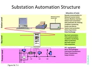
SAS Engineering Tools • SCL is used also to describe all data needed to define system parameters for a single IED • This includes especially the binding of the IED and its functions to the substation itself, in terms of its single line diagram to the communication system • The Substation Configuration Language is based on UML and XML
UML • The heart of object-oriented problem solving is the construction of a model. • The model abstracts the essential details of the underlying problem from its usually complicated real world. • Several modeling tools are wrapped under the heading of the UML™, which stands for Unified Modeling Language™.
UML • The Unified Modeling Language (UML) is a standard language for specifying, visualizing, constructing, and documenting the artifacts of different simple or complex systems. • UML uses mostly graphical notations to express the design of software projects. Using the UML helps project teams communicate, explore potential designs, and validate the architectural design of the system.
UML • The UML is applicable to object-oriented problem solving. • A model is an abstraction of the underlying problem. • The domain is the actual world from which the problem comes. • Models consist of objects that interact by sending each other messages. • Objects have things they know (attributes) and things they can do (services).
XML • Extensible means that it can be advanced to meet specific needs by creating descriptive tags to fit the requirements of the problem domain • Files can be edited using off-the-shelf text editors • Availability of specialized tools
Markup description Markup declaration open Markup declaration close <pickup>1.5</ pickup > Element name Element termination Element content
XML Applications • Part 6 of the IEC 61850 standard specifies a description language for configurations of electrical substation IEDs Substation Configuration Language (SCL) based on XML • It is used to describe IED configurations and communication systems according to parts 5 and 7 of this standard. • Description of the relations between the substation automation system and the substation (switchyard) itself
Substation Configuration Language Components • Substation section: describes the substation single line diagram, and its binding to logical nodes as well as the placement of logical nodes onto IEDs. Thus also the binding of IEDs to substation parts and substation devices is defined.
Substation Configuration Language Components • Communication section: describes the communication connections between IEDs in terms of connecting communication links.
Substation Configuration Language Components • IED section: describes the capabilities (configuration) of one or more IEDs, and the binding to logical nodes on other IEDs. • LNType section: defines which data objects are actually contained within the logical node instances defined for the IEDs.
SCL Files • Data exchange from a system specification tool to the system configuration tool. This file describes the single line diagram of the substation and the required logical nodes. The file extension shall be .SSDfor System Specification Description.
SCL Files • Data exchange from the IED configuration tool to the system configuration tool. This file describes the capabilities of an IED. The file extension shall be .ICDfor IED Capability Description.
SCL Files • Data exchange from the system configuration tool to IED configuration tools. • This file contains all IEDs, communication configuration and substation description sections. • The file extension shall be .SCDfor Substation Configuration Description.
SCL Files • It is an SCD file, possibly stripped down to what the concerned IED shall know. • The file extension shall be .CIDfor Configured IED Description.
SAS Engineering Process • Define the functional specification according to the approved protection, automation and control concepts and user’s standards. This is done using the substation one line diagram and defining: • Protection functions required for each primary substation or system component
SAS Engineering Process • Measurements and status information needed • Controls to be used • Reporting requirements • Monitoring and recording requirements
SAS Engineering Process • Redundancy requirements • Communications architecture • Substation level functions • Other as necessary • All of the above should be produced by a system specification tool that provides as an output an SSD file.
Utility Standards SAS Engineering Process Functional Specification
Benefits • Quite significant • Reduce the costs for system design • Improve factory and site acceptance testing • Improve the maintenance process • Improve the overall quality of the substation automation system