Download
1 / 10
100 likes | 199 Views
Explore light guide efficiency simulations for PMTs with requirements on conversion, trapping, and quantum efficiencies, as well as transport and thermal considerations. Analyze light collection and losses in various setups to enhance detection capabilities.

E N D
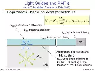
Light Guides and PMT’s (from T. Ito slides, Pasadena, Feb 2007) • Requirements—20 p.e. per event (for particle ID) conv: conversion efficiency Atrap: trapping efficiency pmt: quantum efficiency trans: transport efficiency PMT One or more thermal break(s) TPB coating tpb:Solid angle subtended by the TPB coating at the location of the 3He+n reaction Neuv LHe E. Beise, U Md
Light collection simulation From T. Ito’s slide 3 (Pasadena, Feb 2007) Summary of results from litrani (details to follow): (with 1 thermal break) (assumes perfect surfaces) E. Beise, U Md
Acceptance of UV light on Cell walls Where does the UV light go, as a function of (x,y,z) of generation point? • For -15 cm < z < 15 cm, side walls see 90% of the light • When opposite walls summed, light collection does not depend much on (x,y) location 10 cm 50 cm 10 cm E. Beise, U Md
Adiabatic Guides attached to lucite cell Josh Rehak, U Md 1/22/2008 if perfect optical coupling between guide and detector bend radius = 15 cm downstream upstream 100K photons (400 nm) generatedinto 2pfrom surface of sidewall downstream accepted = 14631 upstream accepted = 10414 total = 25% E. Beise, U Md
Adiabatic Guides attached to lucite cell Josh Rehak, U Md /22/2008 with (1 mm) air gap between detector and guide bend radius = 15 cm downstream upstream 100K photons (400 nm) generated into 2p from surface of sidewall downstream accepted = 8694 upstream accepted = 6832 total = 15.5% E. Beise, U Md
Rectangular Guides vs Adiabatic Guides >300 shapes per adiabatic guide Very complicated to rotate into place in simulation Use much simpler rectangular guides for majority of tests and then scale 100K photons generated (uniformly into 4p) along a single wall no other side walls are in optical contact, no endcaps (w/ air gap between guide & det) bend radius = 15 cm bulk absorption length = 450 cm E. Beise, U Md
How much is lost in endcaps? detector For side walls = 50 cm, (lucite) endcaps = 1.27 cm and optically coupled to side walls (but no emission from ends) 15% reduction in accepted light E. Beise, U Md
Where does the (blue) light go? 100K photons generated along each wall (400K total) (1) lucite side walls (1.27 cm) in optical contact, lucite endcaps optically connected to side walls. A single pair of (rectangular) guides sees (with air gap between guide and detectors) 7600 photons from own wall 2400 from each adjacent wall 1000 from opposite wall = 3.3% total (also, 3% lost into the two endcaps) (2) 8 lightguides, total collected = 13.5% (3.3% per detector pair) (no losses/bounce or surface roughness yet included) E. Beise, U Md
Cast surface absorption: .. 0.2% Machined surface abs.: …. 2.0% Bulk attenuation length: 450 cm Reflections: 0-100 cm: every 1.5 thickness 100-200 cm: every 2.2 thickn. Light guides: - ¼ inch thick - 2 strips 2.5 cm wide - 4 strips 5.0 cm wide Coated wall: 10cm x 50 cm, one piece Reflection survival: 100 cm guide: 0.55 200 cm guide: 0.39 100+200 guide: 0.47 (100+200 bulk attenuation: 0.60 already included in earlier slides) Components of attenuation: guide (cm): 100 200 - Cast surfaces: 0.81 0.74 - 2.5 cm machined: 0.58 0.41 - 5.0 cm machined: 0.76 0.64 Estimated Surface Losses (H.Breuer) E. Beise, U Md
Losses: 1 vs. 2 light guides (H.Breuer) 2 light guides (100 + 200 cm) survival: 0.330{0.231} 1 light guide (100 cm + reflector) survival: 0.378{0.328} … 15% overall improvement{42% for replaced 200cm} due to shorter path length much fewer surface reflections Using: • 100 cm light guide + (100 cm +50 cm wall piece) • 5% reflector loss • Assuming wavelength shifter coating acts like a cast surface (99.8 reflectivity, very iffy!) Needs MC and test verification. E. Beise, U Md