
Uploaded by
michel
0 SLIDES
138 VIEWS
0LIKES
Understanding Voltage: Definitions, Measurements, and Circuit Applications
DESCRIPTION
This lesson provides a comprehensive overview of voltage in electronics, covering essential terms and definitions, common voltage sources, and symbols used in circuit diagrams. Learn about the principal parts of a voltmeter, procedures for accurate voltage measurement, and the application of Ohm's Law in calculating voltage drops in resistive circuits. This foundational knowledge is crucial for anyone working with electrical systems, ensuring a solid grasp of how voltage operates within various electronic components.
Download

1 / 0
Download Presentation 
Understanding Voltage: Definitions, Measurements, and Circuit Applications
An Image/Link below is provided (as is) to download presentation
Download Policy: Content on the Website is provided to you AS IS for your information and personal use and may not be sold / licensed / shared on other websites without getting consent from its author.
Content is provided to you AS IS for your information and personal use only.
Download presentation by click this link.
While downloading, if for some reason you are not able to download a presentation, the publisher may have deleted the file from their server.
During download, if you can't get a presentation, the file might be deleted by the publisher.
E N D
Presentation Transcript
-
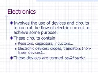
Electronics
Voltage and Its Measurements - Lesson Overview Terms and Definitions Common Voltage Sources Voltage Symbols or Abbreviations and Definitions Principal Parts of a Voltmeter Procedures for Using a Voltmeter Ohm’s Law Formulas for Voltage Drops in Resistive Circuits Polarity in a Resistive Circuit Kirchhoff’s Law of Voltage Current Flow in a Resistive Circuit
- Terms and Definitions Voltage- electrical force or pressure that causes the flow of electrical current (electrons) Volt- the unit of measurement of electromotive force (Note: One volt forces one ampere of current through one ohm of resistance) Voltage drop- difference in voltage measured across a component in a circuit Voltmeter- instrument used to measure voltage
- Common Voltage Sources Common Voltage Sources Batteries Generators/alternators Electronic power supplies Other Alternatives Static Friction Heat Light
- Voltage Symbols or Abbreviations and Definitions EMF (or emf)- electromotive force (Note: EMF is the same as voltage) E (or e)- voltage source or applied voltage V- voltage or voltage drop kV- kilovolt (one thousand volts) MV- megavolt (one million volts) mV- millivolt (one thousandth of a volt) µV- microvolt (one millionth of a volt) VM- voltmeter
- Basic Electrical Measurement Using handheld electronic test tools
- Types of Measurement The most common electrical measurements Voltage Resistance Current Each of these types of measurement has different characteristics. Newer meters measure many more things.
- Measurement Devices Historically, devices could measure only one electrical characteristic. Voltmeters, ammeters, meggers, etc. Different types of measurement require a specific circuit. Newer meters combine all these functions into a single device. This device is called a digital multimeter, or DMM.
- Principal Parts of a Voltmeter (Multimeter) Test leads or probes Red is positive Black is negative or ground
- Principal Parts of a Voltmeter (Multimeter) Function Switches Voltage, current, resistance Direct current, alternating current, Measurement range
- Function Switch Positions
- Function Switch Positions Volts AC Alternating Current
- Function Switch Positions Volts DC Direct Current
- Function Switch Positions Resistance Continuity
- Function Switch Positions Current AC or DC
- Current Measurement Switch the lead from here
- Current Measurement Switch the lead To here
- Principal Parts of a Voltmeter (Multimeter) An analog meter has multiple use scales Range switch (to select proper range) Note: A range position should be selected, when possible, for middle-third region of a scale where the meter is most accurate. If unknown voltage, start at high range and work down one step at a time.
- Principal Parts of a Voltmeter (Multimeter)
- Voltage Measurement The circuit is energized Dangerous voltages may exist! Two types of measurement The measurement is taken across a component using both test leads Measurement from a test point to a reference point (like ground) using both test leads The meter is NOT part of the circuit
- Resistance Measurement The circuit is de-energized. The meter provides an internal reference voltage. Caution: measuring an energized circuit can be dangerous or lead to error. The component to be measured may need to be removed from the circuit. The meter has an internal reference circuit that the component value is compared to.
- Current Measurement The meter needs to be set up before the measurement takes place. Leads are moved to the Amp position. With circuit power off, the meter leads are placed in series with the circuit. A component lead or jumper may need to be removed to allow this. Once leads are set up and the proper current range is selected, the circuit is energized.
- Current Measurement The meter becomes part of the circuit. Current is the same everywhere in a series circuit. NEVER measure across a component when the meter is in current mode. The meter has low internal resistance in this measurement mode. If you do, the internal fuse WILL blow. A common problem with multimeters is the blown fuse, which will prevent future current measurement.
- Other Measurements Continuity Diode test also used for transistors Temperature Capacitance Frequency
- Procedures for Using a Voltmeter (Multimeter) Hold probes by insulated part. Select AC or DC voltage. Set range switch for correct range. Use correct polarity of leads or probes. negative or common probe (black) toward negative of power supply positive probe (red) toward positive of power supply
- Procedures for Using a Voltmeter (Multimeter) Connect voltmeter in parallel with load.
- Procedures for Using a Voltmeter (Multimeter) Touch the probe tips to the circuit. Read voltage on meter. Remove probes.
- Follow The Law! All electrical measurements are based on Ohm’s Law. Ohm’s Law describes the relationships between voltage, current, and resistance.
- The Ohm’s Law Circle Cover the value you want to solve for. The formula to use is the two remaining values. V V = I x R I R = I = I
- Formulas for Voltage Drops in Resistive Circuits
- Polarity in a Resistive Circuit End nearer the negative of supply is negative (use black lead) End nearer the positive of supply is positive (use red lead)
- Kirchhoff’s Law of Voltage The algebraic sum of the voltage drops around a closed loop must equal the applied voltage. Ea = VR1 + VR2 + VR3 +…
- Current Flow in a Resistive Circuit Negative to positive Resultant potential across resistance (voltage drop)
- How DMMs Measure Voltage There is an electronic gate inside the meter that opens and closes while taking the measurement. The time the gate is “open” is a function of the amount of voltage being measured (e.g., the larger the voltage, the longer the gate is held open). These pulses are counted and the larger the count, the greater the voltage being measured. The output is then presented on an LED or LCD display. This process works for both voltage and current.
- Voltage Measurement Summary Select AC or DC voltage as necessary. The black (ground) test probe goes into the COM input connection; the red test probe goes into the V input connection. If the DMM has manual ranging only, select the highest range, so as not to overload the input. Touch the probe tips to the circuit across a load or power source (in parallel to the circuit). View the reading, being sure to note units.
- AC Voltage AC voltage is constantly changing. We need a number to represent the value. There are several types of values used Peak to peak Average RMS
- RMS vs. Average RMS is the Root Mean Square or effective heating value of any AC voltage or current waveform. RMS is the equivalent DC heating value of an AC waveform. Power consumed is the same for both AC and DC sources when the Vacrms equals Vdc. Average is the DC equivalent voltage of the AC signal.
- Why RMS? The RMS voltage value determines how much heat the voltage amount will create in a component. RMS is an AC voltage value that creates the same heat as the same DC voltage value. Components need to have a power rating that is the same for AC or DC voltage. 5 VRMS = heat = 5 VDC
- Measuring Resistance Turn the power OFF to the circuit. Select the resistance setting (Ω). Plug the black test probe into the COM input jack; plug the red test probe into the Ω input jack. Connect the probe tips across the component or portion of the circuit for which you want to measure the resistance value. View the reading, and make sure to note the unit of measurement. ohms (Ω), kilohms (kΩ), or megohms (MΩ).
- Current Measurement An ammeter has low resistance in the current measurement mode. Current measurements are made with the circuit energized. creates safety hazards makes it difficult to measure current For these reasons, current is often measured with a different type of probe. clamp on ammeter
- Measuring Current Turn off power to the circuit. Cut or unsolder the circuit, creating a place where the meter probes can be inserted. Select A~ (AC) or A (DC) as desired. Plug the black test probe into the COM input jack. Plug the red test probe into the amp or milliamp input jack (depending on the expected value of the reading).
- Measuring Current (continued) Connect the probe tips to the circuit across the break so that all current will flow through the DMM (a series connection). Turn the circuit power back on. View the reading, being sure to note the unit of measurement. Unplug the leads when done.
- DMM Display A DMM display is not like a calculator. A four digit calculator can read from 0 to 9999. A multimeter that can display four digits could historically have only a 1 in the leftmost (or most significant) decimal place. If the MSD value was not 1, the digit is left blank (only three digits are used). This type of display is called a 3 ½ digit display.
- Example 3 ½ digit display
- Example 199.9 volts is displayed using all four digits. )
- Example 199.9 volts is displayed using all four digits. 200 volts is displayed using only three digits with no decimal place (the “1” space is left blank).


More Related