LUCID status
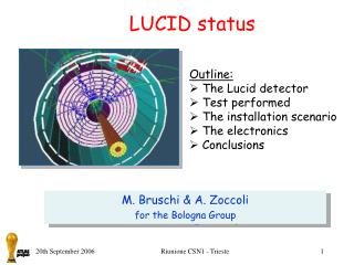
LUCID status. Outline: The Lucid detector Test performed The installation scenario The electronics Conclusions. M. Bruschi & A. Zoccoli for the Bologna Group. The LUCID detector. Fibres. Winston Cones. LUCID : “ LU minosity measurement using C erenkov I ntegrating D etector.

LUCID status
E N D
Presentation Transcript
LUCID status • Outline: • The Lucid detector • Test performed • The installation scenario • The electronics • Conclusions M. Bruschi & A. Zoccoli for the Bologna Group Riunione CSN1 - Trieste
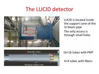
The LUCID detector Fibres Winston Cones LUCID : “LUminosity measurement using Cerenkov Integrating Detector Goals: - provide a relative luminosity measurement (integrated and bunch by bunch); - provide η-coverage for diffractive physics Two detectors x 168 Al tubes filled with Isobutane at 1 or 2 Bar pressure Winston cones at the end of the tubes bring the Cerenkov light onto quartz fibers. Riunione CSN1 - Trieste
Activities of the Group since Feb.06 • Main activities of the LUCID Group after the Test Beam 05 which provided a light yield of ~5 p.e. : • development and optimization of the Monte Carlocode to reproduce the detector performances. • Test on bench @ CERN and test beam @ DESY to check the detector performances and tune the MC. • Production of new improved detector parts (tubes, Winston cones, fibers). • Development of the electronics project • Discussion of the detector design and of the installation strategies Riunione CSN1 - Trieste
Test on bench @ CERN • Tubes: • Mechanically polished • Electro-polished and mech. polished • Mylar liner • Old tubes (used in 2005 TB) Goal of the measurements: Understand the detector performances and check the improvements on new parts. Tested material: • Winston Cones: • Ø 4 mm and Ø 3 mm (new design) • Old cones Ø 3 mm (used in 2005 TB) • Fibers bundles: • PUV 500, 700, FSU 600 • Old fibers HUV1000 (used in 2005 TB) Riunione CSN1 - Trieste
Test on bench: quantities studied Riunione CSN1 - Trieste
Test Bench results: new tubes Mylar tube New tube Old tube Old tube New tube Aluminum tubes mechanically polished show a 10% improvement w.r.t old tubes. Close to the Mylar solution. Riunione CSN1 - Trieste
Test Beam @ DESY Test beam performed on the 6 GeV electron beam @ DESY in August 2006 Tested different detector configurations: • Old tube, old WC cone, old fiber bundle • New tubes, new WC cones, new fiber bundles • New tube, new WC cone coupled directly to a single PM a la CDF (backup solution for LUCID) • Exchanged the detector configurations in order to determine the improvements on the different parts. First results from the data analysis. Riunione CSN1 - Trieste
TB results: fiber detector Fit each single-channel spectrum: add the results or use calibrations and pedestals (from fits) to rescale each event and obtain the total distribution for each tube Riunione CSN1 - Trieste
TB results: fiber detector II Central fibers ~11.5 p.e. Lateral fibers Central fibers Middle fibers lateral fibers ~9.5 p.e. Maximum light yield: ~10-12 p.e. ~ factor 2 improvement w.r.t. 2005 Little bit less than expected from test on bench. Some more improvements needed (2 track resolution etc.) Riunione CSN1 - Trieste
R2496 TB results: single PM ADC spectra, with two peaks: A) Cerenkov light only from gas B) Cerenkov light from gas and PM quartz window A B Riunione CSN1 - Trieste
TB results: single PM - II Maximum light yield: ~60-85 p.e. in gas ~40 p.e. in quarzt w. ~100-125 p.e. in tot. Close to the CLC (CDF) performances, with a non optimized system. • Solution appealing for the number of p.e., but need to verify: • Radiation hardness of complete PMT system. • Background Cerenkov light in the PMT window from primary & secondary particles. • PM activation, lifetime and Mechanical design. Riunione CSN1 - Trieste
Conclusions on the TB results Work to be done in the next few months: • optimization of the baseline solution to further improve performances. (produce new detector parts, test on bench etc.). • Careful verification of the feasibility of the backup option (background, rad. hard. tests etc.). • Radiation tests for the baseline (fiber, epoxy etc.) and for the backup solution (PMT, cables etc.) are needed now Work is starting now! • Optimization of the Monte Carlo • Test Beam of the final detector before the installation (December 2006). Riunione CSN1 - Trieste
LUCID detector deployment-I • The proposed plan for a full LUCID deployment includes the installation of a subset of LUCID detector in 2007. • The LUCID group is aiming for a full installation of the LUCID in the first long shutdown after end 2007. • This reduced detector deployment in 2007, will be sufficient to allow the preliminary study of the following: • Backgrounds from secondary in the LUCID detector; • Beam related backgrounds; • Timing; • The front-end and backend readout electronics; • The installation and alignment of the LUCID detector; • The gas supply system; • The effect of heat from the bake-out jacket on the LUCID detector • First luminosity measurements. Riunione CSN1 - Trieste
Baseline fibre-optic readout Single PMT LUCID detector deployment-II • The reduced detector deployment will include the complete LUCID pressure vessel, alignment system and gas system. • We plan to readout only ~10 tubes/end. Most of the channels will be readout via fused-silica fibres to remote MaPMTs . • The FE readout will be placed in the vicinity of the MaPMTs - the resulting signals will be driven to the BE readout in USA15. We expect to use an initial version of the final LUCID electronics. • A few channels will be equipped with asinglePMT placed on Winston Cone ends. These PMTs will be readout, via an amplification stage, in USA15, for timing and light collection studies. • The full LUCID detector will be installed during the first long shut-down. Riunione CSN1 - Trieste
The LUCID readout Placing MaPMTs Readout paths • Baseline: • MaPMTs placed in the shielding • MAROC chip placed by the MaPMTs • Drivers boost signal out • Cables go direct to USA15 980 100M) • Radiation level in the vicinity of the MaPMTs is 35 Grays/Yr Cable lengths Riunione CSN1 - Trieste
The LUCID FED cards RX Digital Board TTCRQ, ELMB128A,volt. reg. MAROC Boards TX Digital Board GOL, FPGA, TX Connectors Board (HV,LV,RX, TX, analog) Base board (connectors,signals routing, MAROC prog.FPGA ) ANALOG board (ampl.+line driv.) The front end system is now modular so allowing scalability The MAROC Board and part of the ANALOG board has been developed by LUND (thanks!) Riunione CSN1 - Trieste
The FED (digital part) • The TX digital board designed is in production • The other two cards (RX, Connectors) have been mostly defined (6 more weeks work) • In order to define the Base Board we need to fix the MAROC I/O (B.L.) • All the components (electronics, connectors –except HV) have been defined • A prototype of the front end card (MAROC) should be ready toward the middle/end of November Riunione CSN1 - Trieste
Electronics/ The analog test board • The analog test board has been designed with the aim to provide the possibility to test the analog part of the MAROC chip based front end cards • It will allow to test also single anode PMT based readout scheme • It is meant to be an important tool that should allow us to understand the detector even in case of delay in the production of a prototype for the MAROC chip based front end cards by using commercially available VME modules for the DAQ • All its parts already in production/ prototype should be ready beginning of October Riunione CSN1 - Trieste
Electronics/ The Analog Test Board Riunione CSN1 - Trieste
Conclusions -I • New detector parts (tubes, cones, fibres) have been produced and tested on bench and at the DESY test beam in August 2006. • The TB results indicate factor of ~2 improvements over last test beam. Some more improvements are expected in the next detector version • A test beam on the final detector will be performed in December 2006. • Radiation hardness studies on single PMT and fiber bundles are starting now. • New installation scheme for LUCID has been studied. Partial detector deployment foreseen in 2007 Riunione CSN1 - Trieste
Conclusions-II • MAROC2 chip including modifications for LUCID delivered on July. First tests look promising. • The design of the front-end electronics is started and it is on track (although we still need a confirmation of the performances of the detector) • The most important part of the FED is already under production • The Analog Test Board (Backup solution for tests but also for the 2007 installation) is in advanced status of production (prototype expected for beginning of next October) • The project is now modular. Moreover, it can be easily adapted in case we will decide for the LUCID readout backup solution • The development of the readout and trigger electronics could be a bit relaxed since we can use already available pieces of DAQ to give a luminosity measurement as soon as the front end electronics will be available Riunione CSN1 - Trieste
Backup slides Riunione CSN1 - Trieste
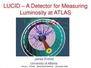
MBTS TILE LUCID position Front face of LUCID end is ~17m from the IP. Projective geometry. Acceptance covered 5.4 <|η|< 6.1 LUCID region 6-7 Mrad/year at 1034 cm-2s-1 Riunione CSN1 - Trieste
LUCID position (2) • Planned installation after the Big Wheels A/C. Riunione CSN1 - Trieste
Baseline fibre-optic readout Miniature PMT Backup solution (under study) PMT • Place single miniature PMTs directly onto the end of each Winston cone? • Advantages: • More light because of direct coupling • Lower electronics cost • Swap quartz fibres for (cheaper) signal cables • Need to study: • Radiation hardness of complete PMT system • Background Cerenkov light in window from primary & secondary particles • Activation • Mechanical design First check @ the DESY Test Beam HAMAMATSU R2496 Riunione CSN1 - Trieste
Richieste finanziarie 2007 Gruppo BO-Lumi: 16.6 FTE + 0.85 Tecnol.= 17.5 FTE Missioni interne: - metabolismo 17.5 k€ Missioni estero: - metabolismo (17.5 FTE x 1.5MU x 4.4k€) 115.5 k€ - C&I (6 mesi x 3 FTE x 4.4 k€) 79.2 k€ - Presa dati (3mesi x 2FTE x 4.4 k€) 26.4 k€ Consumo: - metabolismo 26.0 k€ Inventario: - 2 postazioni di lavoro 4.0 k€ Costruzioni apparato: - (vedi trasparenza successiva) 45.0 k€ Riunione CSN1 - Trieste
Richieste costr. Apparati 2007 Riunione CSN1 - Trieste
Test Bench results: old test beam parts Good understanding of the detector performances. Riunione CSN1 - Trieste
Expected improvements Expected improvements in light yield based on test bench results: • Tubes: improvements in the internal surface (~ 1.1) • Winston cone: new design + internal surface (~ 1.4 - 3) • Fibers: improve fiber quality. Less attenuation (at 300 nm), Larger angular acceptance and larger (core)/(clad) area ratio (0.78 compared to 0.68) plus enlarge the light spectrum sensitivity ( ~1.6) Expected improvements in light collection: factor ~2 – 4 Next steps: • Test beam @ DESY from the 31st of July until the 12th of August to test the new detector performances • Further detector optimizations • Test beam @ CERN in November to test the final detector Riunione CSN1 - Trieste
FED MAROC PMF ANALOG CARD Riunione CSN1 - Trieste