Download
1 / 60
600 likes | 782 Views
Built-In Self-Test and Calibration of Mixed-signal Devices. Wei Jiang Ph.D. Dissertation Proposal June 11, 2009. Committee Members: Fa F. Dai Victor P. Nelson Adit D. Singh. Advisor: Vishwani D. Agrawal. Outline. Overview Background Built-in Test and Calibration Approach

E N D
Built-In Self-Test and Calibration of Mixed-signal Devices Wei Jiang Ph.D. Dissertation Proposal June 11, 2009 Committee Members: Fa F. Dai Victor P. Nelson Adit D. Singh Advisor: Vishwani D. Agrawal
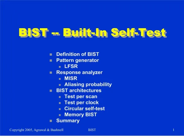
Outline Overview Background Built-in Test and Calibration Approach Current Progress Future Work Conclusion Wei Jiang
Overview • Issues • Parameter deviation • Process variation • Problem • Design variation-tolerant process-independent technique for mixed-signal devices • Approach • Test and characterization of mixed-signal devices • Output calibration Wei Jiang
Mixed-signal Device • Analog and digital circuitry • Digital controllable • Typical devices • Converters, digital-to-analog/analog-to-digital • Amplifier Wei Jiang
Testing of Mixed-signal Devices • Defects and faults • Catastrophic faults (hard faults) • Parametric faults (soft faults) • Test approaches • Functional test (specification oriented) • Structural test (defect oriented) Wei Jiang
Challenges • Analog circuitry • No convincing fault models • Difficult to identify faults • Device parameters more susceptible to process variation than digital circuitry • Fault-free behavior based on a known range of acceptable values for component parameters • Large statistical process variation effects in deep sub-micron MOSFET devices Wei Jiang
Process Variation • Parameter variation in nanoscale process • Yield, reliability and cost • Feature size scaling down and performance improvement • Effects on digital and analog circuitry • Analog circuitry more affected by process variation • Parameter deviation severed in nanoscale process • System performance degraded when parameter deviation exceeds beyond tolerant limits Wei Jiang
Outline Overview Background Built-in Test and Calibration Approach Current Progress Future Work Conclusion Wei Jiang
Typical Mixed-Signal Architecture Wei Jiang
Mixed-Signal System Test Architecture * F. F. Dai and C. E. Stroud, “Analog and Mixed-Signal Test Architectures,” Chapter 15, p. 722 in System-on-Chip Test Architectures: Nanometer Design for Testability, Morgan Kaufmann, 2008. Wei Jiang
Mixed-Signal System Test Architecture • Digital system • Digital I/O • Digital signal processor (DSP) • TPG and ORA and test control unit • Digital loopback • Mixed-signal system • DAC and ADC • Analog loopback • Analog system • Analog circuitry • Analog signal I/O • Analog I/O loopback Wei Jiang
Test Criteria • Digital circuitry test • Defect-oriented test • Defects cat be detected by wrong output response for specific test pattern • Analog circuitry test • Specific-oriented test • Parameter deviations vs. the acceptable tolerant limit Wei Jiang
Typical Mixed-Signal Devices • DAC – digital-to-analog converter • Digital inputs; analog outputs • ADC – analog-to-digital converter • Analog inputs; digital inputs • Digital Controlled Amplifier • Analog inputs/outputs with digital controlling inputs • Analog transfer function controlled by digital device, e.g. microcontroller • Gain/distortion/nonlinearity respond to digital controlling signal Wei Jiang
Existing Testing Approach Oscillation BIST LFSR-based TPG FFT-based BIST Wei Jiang
Linearity Problem • LSB – least significant bit • The minimum measurement for of analog value • Represented by 1 digital bit • Non-linearity Error • DNL – differential non-linearity • INL – integral non-linearity Wei Jiang
Non-linearity Error of ADC/DAC Non-linearity error Non-linearity error Wei Jiang
Other Characteristics • Frequency response • Bandwidth • Noise • SNR – signal-to-noise ratio • SINAD – signal-to-noise and distortion ratio • Offset, gain, harmonic distortion • Intermodulation distortion Wei Jiang
Outline Overview Background Built-in Test and Calibration Approach Current Progress Future Work Conclusion Wei Jiang
Typical Mixed-Signal System with DAC/ADC Wei Jiang
Components Description • Digital circuitry (including DSP) as BIST control unit • Test pattern generation (TPG) and output response analysis (ORA) • Measuring ADC • First-order 1-bit Sigma-Delta modulator • Digital low-pass filter • Measuring outputs of DAC-under-test • Dither DAC • Low resolution DAC • Generating correcting signal for calibration • Calibrated DAC for test of ADC-under-test • ADC Polynomial Fix • Digital process to revise ADC output codes Wei Jiang
Testing Procedure • Self-test of testing and calibrating components • Self-test of BIST control unit (including DSP, TPG/ORA) • Self-test of measuring ADC • Test of dithering DAC by measuring ADC • Test of On-chip DAC • Ramp test of on-chip DAC • Characterizing on-chip DAC by DSP • Calibration of on-chip DAC by dithering DAC • Test of on-chip ADC • Ramp test of on-chip ADC • Characterizing and fixing on-chip ADC outputs by DSP Wei Jiang
Faulty Mixed-Signal Circuitry • Good circuitry • All parameters and characteristics are within pre-defined specified range • Fault-tolerant factor • Post-fabrication and software-controllable • Fault-tolerant factor varies for different application • Trade-off between fault-tolerance of parameter deviation and calibration resolution Wei Jiang
Determine Faulty DAC/ADC • Coefficients representing offset, gain and harmonic distortion exceeding specific limit • Maximum INL error exceeding calibration range (depending on fault-tolerant factor) • ±4LSB for fault-tolerant factor 3 • INL errors of all calibrated outputs must be within ±0.5LSB Wei Jiang
Device Test and Calibration • During BIST • Test DAC/ADC with ramp signals • Measure response of each test code • Obtain INL error for each code • Characterize device by INL error • After BIST • Determine faulty devices by deviation of parameters • Generate correcting signal/data (identical to INL error) for each code • Calibrate DAC/ADC output using correcting signal/data by removing INL error Wei Jiang
The ONLY Problem • Storing all INL errors for every input code of DAC/ADC is impossible • Requiring huge amount of memory • Needing lots of access time to retrieve specific data from memory • Prohibiting cost • Solution • Polynomial fitting • Storing several coefficients instead of all data Wei Jiang
Test Pattern • Test pattern • Ramp code • Least value to most value • Testing time for each pattern depends on the converting speed of measuring ADC • Single-tone and multi-tone test patterns can also be used Wei Jiang
Test of Digital Circuitry Conventional digital BIST technology LFSR-based random test; Scan-based deterministic test Digital loopback conducted Fault-free digital circuitry then used for mixed-signal test May be hardware- or software-based Wei Jiang
Measuring ADC First-order 1-bit sigma-delta ADC Perform self-test before any other mixed-signal test Make sure each components of sigma-delta ADC working Quantization noise Bit-stream output pattern Wei Jiang
Sigma-Delta Modulator Wei Jiang
Sigma-Delta Modulator (cont.) • Advantage • Oversampling and noise-shaping • High resolution and linear results • Resolution depends on OSR (oversampling ratio) • Simple structure and low cost • Disadvantage • Very slow converting speed • Bit-stream output pattern issue for low-order modulation • Requiring high-speed clock • Higher order and/or multi-bit modulation Wei Jiang
Selection of Sigma-Delta Modulator SNR (LSB) Third-order Second-order 17-bit ENOB104.1LSB First-order Oversampling ratio (OSR) Wei Jiang
Digital Filter Sigma-delta ADC consists of sigma-delta modulator and digital filter Low-pass filter (LPF) Integrator Comb filter Wei Jiang
Dithering DAC Low-cost low-resolution DAC Better linearity output with DEM technique Must be tested by measuring ADC before test of on-chip mixed-signal devices Wei Jiang
Resolution of Dithering DAC Estimated DAC resolution (bits) Oversampling ratio (OSR) α=1 2 3 17bits Resolution of dithering-DAC (bits) Wei Jiang
Polynomial Fitting Algorithm • Introduced by Sunter et al. in ITC’97 and A. Roy et al. in ITC’02 • Summary: • Divide DAC transfer function into four sections • Combine function outputs of each section (S0, S1, S2, S3) • Calculate four coefficients (b0, b1, b2, b3) by easily-generated equations Wei Jiang
Third-order Polynomial Wei Jiang
Adaptive Polynomial Fitting • Dynamically choose polynomial degree • Low-order polynomial • Simple to design and implement • Less area and performance overhead • Large fitting error • High-order polynomial • Better fitting results • More coefficients to store • Much more complicated polynomial evaluation circuitry design and heavy area and performance overhead Wei Jiang
Test and Calibration of On-Chip DAC Wei Jiang
Test and Calibration of On-Chip ADC Wei Jiang
General Mixed-Signal Test Variation-tolerant design Digital controlled BIST Digitalized TPG/ORA Self-testable measuring components Characterization of device-under-test by DSP Faulty circuitry determined by characterized parameters Coefficients of output fix/correction signals calculated by DSP Wei Jiang
Outline Overview Background Built-in Test and Calibration Approach Current Progress Future Work Conclusion Wei Jiang
Publications W. Jiang and V. D. Agrawal, “Built-In Test and Calibration of DAC/ADC Using A Low-Resolution Dithering DAC,” NATW’08, pp. 61-68. W. Jiang and V. D. Agrawal, “Built-in Self-Calibration of On-Chip DAC and ADC,” ITC’08, paper 32.2. W. Jiang and V. D. Agrawal, “Built-in Adaptive Test and Calibration of DAC,” NATW’09, pp. 3-8. W. Jiang and V. D. Agrawal, “Designing Variation-Tolerance in Mixed-Signal Components of a System-on-Chip,” ISCAS’09, pp. 126-129. Wei Jiang
Progress Presenting a novel approach to test and calibration DAC/ADC Presenting a method to dynamically determine the order of curve fitting polynomial for INL errors Proved by Matlab simulation theoretically Applicable for digitally controllable mixed-signal devices Wei Jiang
Simulation of DAC Test • 14-bit DAC • 16K ramp codes • INL error up to ±1.5LSB INL of 14-bit DAC (LSB) Indices of 14-bit DAC-under-test Wei Jiang
Simulation (Cont.) INL of 14-bit DAC (LSB) • Fitting results by different order polynomial Indices of 14-bit DAC-under-test Wei Jiang
Best-matching Polynomial Wei Jiang
Fitting Algorithm Third-order polynomial fitting algorithm Adaptive polynomial fitting algorithm Determination of best matching polynomial degree Wei Jiang
Measuring ADC / Dithering DAC • Measuring ADC • First-order 1-bit Sigma-Delta ADC • Higher-order multi-bit Sigma-Delta ADC • Non-Sigma-Delta ADC • Digital low-pass filter • Dithering DAC • Binary weighted DAC Wei Jiang
Current Tasks Modeling and hardware verification of proposed testing approach Programming of third-order polynomial fitting algorithm Implementation and optimization of digital polynomial evaluation circuit Design and verification of the whole test and calibration system Wei Jiang