Download
1 / 21
210 likes | 307 Views
This project focuses on developing a compact Terahertz Free-Electron Laser (THz-FEL) facility with high power radiation output. Key technologies include a high gradient S-band RF gun and a multi-femtosecond laser pulse train. Evaluation tools like ASTRA and Genesis are employed for optimization. The development plan involves pre-bunched FEL and matching micro-bunch spacing to wavelength for efficient radiation generation.

E N D
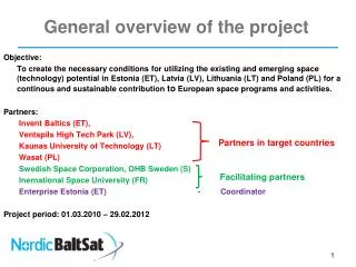
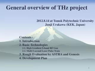
General overview of THz project 2012.8.14 at Tomsk Polytechnic University Junji Urakawa (KEK, Japan) Contents : 1. Introduction 2. Basic Technologies 2-1. High Gradient S-band RF Gun 2-2. Multi f-second Laser Pulse Train 3. Rough Evaluation by ASTRA and Genesis 4. Development Plan
1. Introduction : Compact THz Source Terahertz radiation is an electromagnetic wave in the frequency interval from 0.3 to 10THz. A THz-FEL is a good candidate due to its characteristics of high peak brightness, short duration, and tunable wave length. However, the need for a huge facility and substantial funds limit THz-FEL development. Two important goals are to make the THz-FEL facility compact and to increase its output radiation power. Less than 2m THz Peak power :10MW to 100MW 2
2. Basic Technologies 2-1. High Gradient S-band RF Gun 1.3GeV ATF Linac, results at 80MeV beam. A laser-driven RF gun with a Cs2Te photocathode has been developed at KEK since 2002. This gun has been operated as an electron source for the ATF and generates a beam with an operational intensity of up to 2×10¹⁰ electrons per bunch. In 2008, a new gun incorporating all of the earlier modifications was produced for the ATF. Tests have confirmed a significant improvement of the Q value of the latest model. A typical transverse emittance of 1.3 π mm⋅mrad at 80 MeV has been obtained under the following conditions: solenoid field of 0.18 T, beam intensity of 1×10¹⁰ electrons per bunch, and RF power of 9 MW.
2-2. Multi f-second Laser Pulse Train Pulse duration less than 100fs. Output power more than 20mW. Pulse energy more than 10mJ. Burst amp. Yb-doped Mode-locked fiber laser Oscillator
3. Rough Evaluation by ASTRA and Genesis Astra ( ASpace Charge Tracking Algorithm ) by K. Flottmann (DESY) Genesis by Sven Reiche (PSI) We assume the peak RF field gradient at the cathode surface is 100MV/m, 200pC and the laser injection phase is 20 degree. The bunching factor at 2THz is still high ,0.446 at the wiggler entrance, see next figure. P=P1[Ne + Ne(Ne-1)B(f)], B(f)=∑exp(i2pfzj/c)/Ne , lr=lw(1+K2)/(2g2) 6 Above shows bunching factor dependence at the wiggler entrance on laser injection phase.
Right figure shows bunching factor dependence on total charge assuming Micro-bunch charge is uniform. We need higher gradient acceleration, lower total charge and about 20 degree laser injection phase to keep a high bunching factor. For example, we assume the peak field gradient at the cathode surface is 120MV/m and laser injection phase 20 degree. Then, electron beam energy is 5.68MeV. Also, we consider the wiggler period length 30mm and 2THz radiation (wave length 150mm). g=12, K=0.873. Uniform laser size on cathode 1.0mmf, total charge 25pC 7 14 MW peak power at 0.3m position 170 fs (FWHM), peak current=147A
持帰不可 14MW at 0.3m 25pC/0.170ps=147A, injection phase 20 degrees 120MV/m, 5.68MeV 60MW at 0.4m 25pC/0.136ps=184A, injection phase 20 degrees 140MV/m, 6.66MeV P=P1[Ne + Ne(Ne-1)B(f)], B(f)=∑exp(i2pfzj/c)/Ne , lr=lw(1+K2)/(2g2), K:tune the gap to make the resonance. High gradient acceleration: shorter bunch length (100MV/m-140MV/m) earlier laser injection phase: highbunching factor High Peak Powerradiation(20-10-1) 110MW at 0.3m 30pC/0.120ps=250A, injection phase 1 degrees 140MV/m, 6.53MeV THz peak power 100MWgeneration will be possible. High gradient acceleration gun is essential. 100mJ/pulseTHzsource will be 1mJ-fs laser We have to take care the shielding effect to CSR, maybe.
For example, we assume the peak field gradient at the cathode surface is 120MV/m and laser injection phase 20 degree. Then, electron beam energy is 5.68MeV. Also, we consider the wiggler period length 30mm and 2THz radiation (wave length 150mm). g=12, K=0.873 Uniform laser size on cathode 1.0mmf, total charge 25pC 14 MW peak power at 0.3m position 170 fs (FWHM), peak current=147A My colleague, Prof. Yan of Osaka University, demonstrated the generation of 100fs single electron bunched beam and obtained the single-shot Ultrafast Electron Diffraction (UED) using our RF gun cavity. In this experiment, the time resolution was 20fs in sigma. Electron beam: 3 pC, 3 MeV, 10 Hz operation Sample: ~180nm-thick single-crystal Si 20 shots The single-shot measurement was succeeded. Single-shot 9
Simulation results At cathode 38cm drift space At the entrance of wiggler 0.68MW at 0.4m 12.5pC/0.214ps=58A, injection phase 20 degrees, 100MV/m, 4.7MeV 12cm 38cm 30~50cm 20cm 10cm
4. Development Plan Essential points : Pre-bunched FEL, Dynamical bunching in RF gun cavity which means faster laser injection phase less than 20 deg., Micro-bunch spacing should be matched to wavelength, Late micro-bunch makes the bunching of former micro-bunches in resonated Undulator. 6 ps 2 ps 200~300 fs Time structure of 4 micro laser train for 500GHz super radiation from Undulator 500GHz microwave generation Generation of Comb beam in the RF Gun Cavity Problem: beam loading effect due to multi micro-bunch and tuning on undulator field by pole-gap which makes the FEL resonance. If we accept low micro-bunch charge, say 100pC or less, and not many micro-bunch, say 10 or less, above problems can be overcame.
50MeV S-band accelerator LUCX THz Detector and Imaging Developments Advanced Accelerator Facility from 2008 to 2012 for Quantum Beam R&D SBD detector (1st stage) Maximum Energy 50MeV Maximum Beam Power 156.26MeV mA SBD detector development at LUCX : Measuring micro-wave around 300GHz 12 12 Vis./UV detector γ detector
Recent plan for LUCX accelerator • To downsize the accelerator, we have planed to install a 3.6cell rf-gun and a 12cell booster. • 3.6cell rf-gun • Beam test has been started from Jan 2012. • 12cell booster • This booster is installed now. 3m accelerating tube 1.6cell Rf-gun Wiggler 3.6cell Rf-gun 12cell booster CDR Target and MW Cavity THz Target
LUCX Facility, FSTB LUCX accelerator tunnel Nd:YAG KLY#0 KLY#1 FSTB LUCX control room Modulator #1 Modulator #0 TPU-KEK-RHUL Workshop on THz radiation generation
NLPR passive mode lock oscillator (162.5MHz) 162.5MHz, 350fsec pulse duration, 43mW
1.3GHz seed laser produced by optical resonator and fiber oscillator. If we use high finesse thin optical cavity, we can generate micro bunches train within 8psec. For example, two mirror cavity with the distance of 300mm can generate laser pulse train with pulse spacing of 2psec.
Set-up for fiber amplification test Pulse duration from 100fs to 400fs using fiber laser is generated by simple system.
LUCX “2012 UPGRADE”:THZ, 12-CELL BOOSTER TPU-KEK-RHUL Workshop on THz radiation generation
THz collaboration TPU-KEK-RHUL Workshop on THz radiation generation