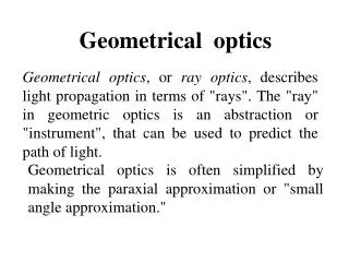
Geometrical Optics
Chapter 24- Review. Geometrical Optics. Refraction. Snell’s Law n 1 sin θ 1 = n 2 sin θ 2. Section 24.3. Critical Angle. From Snell’s Law, with θ 2 = 90°, θ 1 = θ crit

Geometrical Optics
E N D
Presentation Transcript
Chapter 24- Review Geometrical Optics
Refraction Snell’s Law n1 sin θ1 = n2 sin θ2 Section 24.3
Critical Angle • From Snell’s Law, with θ2 = 90°, θ1 = θcrit • When the angle of incidence is equal to or greater than the critical angle, light is reflected completely at the interface Section 24.3
Drawing A Ray Diagram • Three rays are particularly easy to draw • There are an infinite number of actual rays • The focal ray • From the tip of the object through the focal point • Reflects parallel to the principal axis Section 24.4
Mirror Equation Section 24.4
Mirror Equation and Magnification • The mirror equation can be written in terms of the focal length • The magnification can also be found from the similar triangles shown in fig. 24.30 Section 24.4
Sign Convention, Summary Section 24.4
Rays for a Converging Lens • The parallel ray is initially parallel to the principal axis • Refracts and passes through the focal point on the right (FR) • The focal ray passes through the focal point on the left (FL) • Refracts and goes parallel to the principal axis on the right • The center ray passes through the center of the lens, C Section 24.5
Thin-Lens Equation • Geometry can be used to find a mathematical relation for locating the image produced by a converging lens • The shaded triangles are pairs of similar triangles Section 24.5
Thin-Lens Equation and Magnification • The thin-lens equation is found from an analysis of the similar triangles • The magnification can also be found from the similar triangles shown • These results are identical to the results found for mirrors Section 24.5
NEW stuff Ch 24
The Eye Compared to a Lens Section 24.6
The Eye • The eye is a complicated structure but can be understood using the principles of refraction and the properties of light • Path of light in the eye • Light enters through the cornea • Passes through a liquid region called the aqueous humor • Goes through a lens • Enters a gel-like region called the vitreous humor • Finally to the retina • The retina contains light-sensitive cells that convert light into electrical signals carried to the brain by the optic nerve Section 24.6
Corneal Refraction • The indices of refraction are different for different parts of the eye • Vary from about 1.33 to 1.40 • The biggest index change and the largest refraction occur when light first enters the cornea • Snell’s Law and geometry can be used to determine the focal length of the corneal “lens” in the eye Section 24.6
Properties of the Eye • For the simplified model of the eye shown in fig. 24.46, the focal length of the eye is approximately 3.5 R • This is about 1.5 R behind the retina • In reality, the cornea protrudes slightly from the eye • The eye is not truly spherical • R is really the radius of curvature of the cornea • (Check? Feel your eye while it’s closed?!) Section 24.6
Lens of the Eye • The lens is inside the eye • Light passes through the lens after being refracted by the cornea • To simplify the model, assume the lens is just outside of the eye • The lens is a converging lens • For a normal person, ƒlens ~ 25 cm Section 24.6
Lens Maker’s Formula • The focal length of a lens is related to the radii of curvature of the two surfaces forming the lens • The relationship is given by the lens maker’s formula • This form applies only to the double convex lens shape and assumes the lens is in air • More general forms of the formula can be used for other situations Section 24.6
Lens Maker’s Formula and the Eye • Assume the radii of curvature are equal and a focal length of 25 cm is needed • R = 0.21 m • The radius of curvature of the eye is several times larger than the diameter of the eye • This is consistent with a real eye • The front surface of the lens in the eye is rather flat, indicating a large radius of curvature • The actual lens in the eye can change shape to allow for objects at different distances to focus on the retina Section 24.6
Rainbow • An incident ray from the Sun is refracted when it enters a water droplet • The refracted angle depends on the color of the light • Rays for different colors travel at different angles inside the droplet • When light reaches the back surface, a portion is reflected • The reflected rays are refracted again when they leave the droplet • The outgoing rays emerge over a range of angles • Different colors of a rainbow appear at different positions (angles) in the sky Section 24.7
Twinkling Stars • The index of refraction of air depends on its temperature and pressure • The index of refraction varies from place to place in the atmosphere • Each small region acts like a small lens or prism • These “lenses” change from moment to moment • The deflection of rays through these “lenses” also change from moment to moment • This causes the stars to “twinkle” Section 24.7
Aberrations • The ray diagrams and equations used assumed all the rays from an object intersect at a single image point • The images formed by real mirrors and lenses suffer from effects called aberrations • Aberrations are deviations from the ideal images encountered so far Section 24.8
Chromatic Aberration • Is related to dispersion • Different colors are actually diffracted by different amounts • The focal length of a lens is different for each color • Multiple lens can be used to minimize the effect Section 24.8
Spherical Aberration • In real situations, rays that are not exactly on the axis will not focus at the ideal image points found for lenses and mirrors • These deviations are called spherical aberrations since they are due to the spherical shape of the mirror or lens • Using a parabolic shape can eliminate spherical aberration Section 24.8
Chapter 25 Wave Optics
Wave Optics • The field of wave optics studies the properties of light that depend on its wave nature • Originally light was thought to be a particle and that model successfully explained the phenomena discussed in geometric options • Other experiments revealed properties of light that could only be explained with a wave theory • Maxwell’s theory of electromagnetism convinced physicists that light was a wave
Wave vs. Geometric Optics • The wavelength of light plays a key role in determining when geometric optics can or cannot be used • When discussing image characteristics over distances much greater than the wavelength, geometric optics is extremely accurate • When dealing with sizes comparable to or smaller than the wavelength, wave optics is required • Examples include interference effects and propagation through small openings • Even more experiments led to the quantum theory of light • Light has properties of both waves and particles
Interference • One property unique to waves is interference • Interference of sound waves can be produced by two speakers • When the waves are in phase, their maxima occur at the same time at a given point in space Section 25.1
Interference, cont. • The total wave displacement at the listener’s location is the sum of the displacements of the two individual waves • If two waves are in phase, the sum of their displacements is large • The wave interfere constructively • This produces a large amplitude and a large intensity Section 25.1
Interference, final • The maximum of one wave can coincide with the minimum of the other wave • These waves are out of phase • The interference is destructive when the waves are out of phase • If the waves are 180° out of phase, the sum of the displacements of the two waves is zero Section 25.1
Conditions for Interference • Two or more interfering waves travel through different regions of space over at least part of their propagation from source to destination • The waves are brought together at a common point • The waves must have the same frequency and must also have a fixed phase relationship • This means that over a given distance or time interval the phase difference between the waves remains constant • Such waves are called coherent Section 25.1
Coherence • The eye cannot follow variations of every cycle of the wave, so it averages the light intensity • For waves to interfere constructively, they must stay in phase during the time the eye is averaging the intensity • For waves to interfere destructively, they must stay out of phase during the averaging time • Both of these possibilities involve the wave having precisely the same frequency Section 25.1
Coherence, cont. • With slightly different frequencies, the interference changes from constructive to destructive and back • Over a large number of cycles, the waves average no interference Section 25.1
Michelson Interferometer • The Michelson interferometer is based on the interference of reflected waves • Two reflecting mirrors are mounted at right angles • A third mirror is partially reflecting • Called a beam splitter Section 25.2
Michelson Interferometer, cont. • The incident light hits the beam splitter and is divided into two waves • The waves reflect from the mirrors at the top and right and recombine at the beam splitter • The only difference between the two waves is that they travel different distances between their respective mirrors and the beam splitter • The path length difference is ΔL = 2L2 – 2L1 Section 25.2
Michelson Interferometer, final • The path length difference is related to the wavelength of the light • If N is an integer, the two waves are in phase and produce constructive interference • If N is a half-integer the waves will produce destructive interference Section 25.2
Interference Conditions • For constructive interference, ΔL = m λ • For destructive interference, ΔL = (m + ½) λ • m is an integer in both cases • If the interference is constructive, the light intensity at the detector is large • Called a bright fringe • If the interference is destructive, the light intensity at the detector is zero • Called a dark fringe Section 25.2
Measuring Length with a Michelson Interferometer • Use the light from a laser and adjust the mirror to give constructive interference • This corresponds to one of the bright fringes • The mirror is then moved, changing the path length • The intensity changes from high to zero and back to high every time the path length changes by one wavelength • If the mirror moves through N bright fringes, the distance d traveled by the mirror is Section 25.2
Measuring Length, cont. • The accuracy of the measurement depends on the accuracy with which the wavelength is known • Many laboratories use helium-neon lasers to make very precise length measurements • A similar type of interference effect is used to read information from CDs and DVDs Section 25.2
LIGO • LIGO – Laser Interferometer Gravitational Wave Observatory • Designed to detect very small vibrations associated with gravitational waves that arrive at the Earth from distant galaxies • By using a long distance between the beam splitter and the mirrors, the LIGO interferometers are sensitive to very small percentage changes in that distance Section 25.2
Thin-Film Interference • Assume a thin soap film rests on a flat glass surface • The upper surface of the soap film is similar to the beam splitter in the interferometer • It reflects part of the incoming light and allows the rest to be transmitted into the soap layer after refraction at the air-soap interface Section 25.3
Thin-Film Interference, cont. • The transmitted ray is partially reflected at the bottom surface • The two outgoing rays meet the conditions for interference • They travel through different regions • One travels the extra distance through the soap film • They recombine when they leave the film • They are coherent because they originated from the same source and initial ray Section 25.3
Thin-Film Interference, final • The index of refraction of the film also needs to be accounted for • From the speed of the wave inside the film • The wavelength changes as the light wave travels from a vacuum into the film • The frequency does not change • The number of extra wavelengths is Section 25.3
Frequency of a Wave at an Interface • When a light wave passes from one medium to another, the waves must stay in phase at the interface • The frequency must be the same on both sides of the interface Section 25.3
Phase Change and Reflection • When a light wave reflects from a surface it may be inverted • Inversion corresponds to a phase change of 180° • There is a phase change whenever the index of refraction on the incident side is less than the index of refraction of the opposite side • If the index of refraction is larger on the incident side the reflected ray in not inverted and there is no phase change Section 25.3
Phase Change and Reflection, Diagram Section 25.3
Phase Changes in a Thin Film • The total phase change in a thin film must be accounted for • The phase difference due to the extra distance traveled by the ray • Any phase change due to reflection • For a soap film on glass, nair < nfilm < nglass • There are phase changes for both reflections at the soap film interfaces • The reflections at both the top and bottom surfaces undergo a 180° phase change Section 25.3
Thin-Film Interference, Case 1 • Both waves reflected by a thin film undergo a phase change • The number of extra cycles traveled by the ray inside the film completely determines the nature of the interference • If the number of extra cycles, N, is an integer, there is constructive interference • If the number of extra cycles is a half-integer, there is destructive interference Section 25.3
Case 1, cont. • Equations are • These equations apply whenever nair < nfilm < n(substance below the film) Section 25.3
Thin-Film Interference, Case 2 • Assume the soap bubble is surrounded by air • There is a phase change at the top of the bubble • There is no phase change at the bottom of the bubble • Since only one wave undergoes a phase change, the interference conditions are Section 25.3
Thin-Film Interference: White Light • Each color can interfere constructively, but at different angles • Blue will interfere constructively at a different angle than red • When you look at the soap film the white light illuminates the film over a range of angles Section 25.3