Geometrical Optics: Lenses and Mirrors Durability
340 likes | 405 Views
Discover the principles and equations of reflection, refraction, and dispersion in optical systems involving lenses and mirrors. Explore topics such as electromagnetic waves in materials, laws of reflection and refraction, and how lenses focus light to form images. Dive into the concept of focal points, object-image relations, and magnification in geometrical optics.

Geometrical Optics: Lenses and Mirrors Durability
E N D
Presentation Transcript
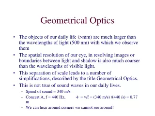
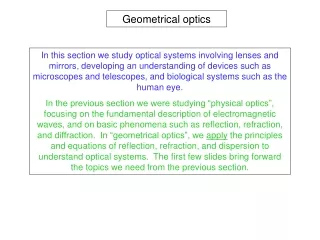
Geometrical optics In this section we study optical systems involving lenses and mirrors, developing an understanding of devices such as microscopes and telescopes, and biological systems such as the human eye. In the previous section we were studying “physical optics”, focusing on the fundamental description of electromagnetic waves, and on basic phenomena such as reflection, refraction, and diffraction. In “geometrical optics”, we apply the principles and equations of reflection, refraction, and dispersion to understand optical systems. The first few slides bring forward the topics we need from the previous section.
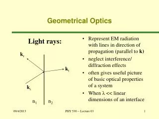
Definition of light rays Recall… The motion of a point on a wave front may be indicated by a direction vector perpendicular to the front. These direction vectors may in turn be connected into single lines or curves, called “rays”. to show the overall motion of a wave front. Typically, a given problem will focus on the behavior of either the wave fronts or the rays, and often only one of the two will be shown. One can always be constructed from the other by drawing perpendicular segments and connecting them.
Electromagnetic waves in materials Recall… Electromagnetic waves travel more slowly in materials than they do in vacuum. For visible light, we are most interested in transparent materials such as glasses, plastics, liquids (especially water), and gases. The ratio of the speed of light in vacuum to the speed in the given material, is called the “index of refraction”, n: The table at right lists the index of refraction for a number of common (and uncommon) materials. You can see the trend that the index of refraction rises with density. If we want to calculate the speed of light in these materials, we solve for v above: Fundamentally:
Laws of Reflection Recall… The Laws of Reflection: (1) The angle of incidence equals the angle of reflection: qa = qr . (2) The incoming and outgoing rays, and the normal, are all in one plane.
Law of Refraction Recall… Light traveling from a medium of lower index of refraction to higher bendstoward the normal. From higher to lower (eg. glass to air) the bending is away. n1 < n2 n1 > n2 n1 n2 n1 n2 The angles are calculated from the Law of Refraction: The critical angle, beyond which total internal reflection occurs, for only: n1 > n2
How a lens focuses light Light rays going through glass plates emerge at their incident angles. But overall bending can be achieved by creating wedges, or “prisms”, of glass. A stack of prisms can bend light toward one line. A symmetric stack of prisms can bend (focus) to a line on its symmetry plane. Smoothing the front and back surfaces into spherical sections will create a lens that can focus incoming parallel rays to a sharp point, known as the focal point.
Focal point of a converging lens As the picture shows at right, rays from infinity (parallel rays), going through a converging lens, will pass through a focal point. This is the way we defined “focal point” on the previous slide. The second picture shows that a point source of light placed at a focal point will cause parallel rays (plane waves) to emerge from the other side of the lens. (1) Every lens has two focal points—one on each side, the same distance from the center, and (2) the lenses pictured here are called “converging” lenses since they bend light toward their optical axis, causing the rays to converge. Notice that, beyond F2 in the top picture, they are diverging.
The “object-image relation” for a thin lens As we know, a lens can focus light to form an image on a screen. In the diagram at right, the object is the arrow on the left, and the image is the inverted red arrow on the right. If we have been given the position and size of the object, the “problem” is to find the position and size of the image. The method we are using here is called “ray tracing”. There are light rays leaving the top of the object in all directions. By “knowing” any two rays, we can find where they cross, and that is the position where the light from the top of the object focuses. We know that (1) the ray traveling parallel to the lens axis will pass through the focal point and, (2) the ray passing through the center of the lens will be straight (for a thin lens). We can calculate the crossing position, Q’, from similar triangles: OPQ sim OP’Q’: OAF2 sim P’Q’F2: then Equate y’/y: Object-image relation Magnification
Images created by light rays passing through lenses From our everyday experience, we know that images we see in mirrors are inverted left-right (“mirror images”). Look at your left hand in a mirror some time, and you’ll see a right-handed image of your left hand. This does not happen with images created by light passing through a lens. The ray tracing construction on the previous slide showed that a converging lens inverts an image in the “y” direction. It does the same thing in the “x” direction. As the picture below shows, the net result is that the image is rotated, but that its “handedness” is preserved. This is still true in systems with multiple lenses, since rays pass through the lenses in succession, and each lens preserves handedness.
Sign rules for object and image distance, and radii of curvature Sign rule for the object distance: When the object is on the same side of the reflecting or refracting surface as the incoming light, the object distance s is positive; otherwise, it is negative. Sign rule for the image distance: When the image is on the same side of the reflecting or refracting surface as the outgoing light, the image distance s’ is positive; otherwise, it is negative. Sign rule for the radius of curvature of a spherical surface: When the center of curvature C is on the same side as the outgoing light, the radius of curvature is positive; otherwise, it is negative.
Focal point of a diverging lens When we introduced the terminology “converging lens”, you may have suspected that lurking in the shadows would be a “diverging lens”. Well, here it is! Any lens that is thinner at the middle than at the edges is a diverging lens, which causes incoming light rays to spread (diverge) instead of focusing (converging). Oddly enough, diverging lenses still have a “focal point”. It is the point from which parallel light seems to come when passed through the lens (upper picture). Also, light focusing to a point can be made parallel if its focal point coincides with that of the lens (lower picture). Fortunately, no new derivations are required. We can use the object-image relation with a diverging lens simply by making the focal length, f, negative! ( We’ll discuss this again later.) Consider a converging lens, f, followed by a diverging lens with f = -f.
The lenses at the top are all examples of converging lenses, and at the bottom, diverging lenses. Consider (1) how this creates convenience, (2) why certain combinations of a and b clearly have no net effect.
“Real” images and “virtual” images In the upper picture, light from the object at P is passing through a converging lens and brought to a focus at P’, where it creates a real image on a screen. Diffuse reflection from the screen is delivering light to the eye. In the lower picture, light from the object at P is passing through a diverging lens. If we look through the lens we see a virtual image that appears to be at location P’. This time the light comes directly from the lens to the eye. As we shall see, however, under the right geometrical conditions, either type of lens can lead to either type of image!
Ray tracing & object-image relation for diverging lenses Recall the rays we constructed to analyze the converging lens, then construct analogous rays for the diverging lens. Note: we have drawn three rays in each case, but any two are enough to specify the image location. If we repeated the derivation of the object-image relation for this lens, we would see that we get the same equation as before as long as we specify the focal length of the diverging lens as a negative number.Diverging lenses are sometimes called “negative lenses”. Object-image relation Magnification
The lensmaker’s equation Imagine that you have a piece of glass, with index of refraction n, that you want to form into a lens. The problem involves determining the radii of curvature for the spherical surfaces needed to achieve a certain focal length. For this we use (without derivation) the lensmaker’s equation: Note that radii with C on the outgoing side, such as R1, , have a positive sign, whereas those on the incoming side have a negative sign. If the two radii are equal in magnitude, this simplifies to:
The pinhole camera Image from a cylindrical oatmeal box camera
The human eye Near-sightedness Far-sightedness
Correcting astigmatism Operator’s manual Lens “power”, in “diopters” For lenses used to correct myopia or hyperopia in the eye, instead of specifying the focal length of the corresponding diverging or converging lens, it is conventional to specify the same information as the “power” of the lens in units of “diopters”. The conversion is simple: the power is the reciprocal of the focal length in meters. Eg. f = .4 m 2.5 diopters for a converging lens, with negative numbers for diverging lenses (since f is negative).
A magnifying glass A normal human eye can focus at a nearest distance of about 25 cm. Usually we use a converging lens to create a real image on a screen. But if that “screen” is our eye, placed just inside the focal point, we will see a large virtual image appearing “nearby”. The virtual image looks much larger than the original because it covers a larger angular range. This causes the image projected on our retinas to be larger by (approximately) the ratio of these angles, which we see as magnification, M: A magnifying glass cannot be used for M greater than about X3 to X4 because the lens becomes thick and introduces aberrations. For higher magnifications, we need an optical microscope. (Below.)
Two lens system For optical systems with more than one optical element (lens, mirror), the image position and magnification are found by stepping through the elements one at a time, finding the intermediate image at each step, until light rays have reached the final image position. At each step, the previous image becomes the new object, and for each element in the system one applies the object-image relation for that particular element:
Optical microscope An optical microscope, otherwise known as a “compound microscope” has two lenses. The one nearest the object (“objective lens”) forms a magnified real image at location F1’ , then the lens nearest the eye (“eyepiece lens”) acts as a magnifying glass to magnify it further. The total magnification M is the product of the magnifications of the objective, m1, and eyepiece, M2. Once again, the near focus limit of the eye at 25 cm is the limiting criterion. Magnification of the objective lens: Magnification of the eyepiece: Combined magnification: MEPI
Refracting telescope Like the compound microscope, the refracting telescope uses an objective lens to create a real image at a location within the tube, and this image is then viewed with an eyepiece lens to magnify the image further. Like the magnifying glass, the total magnification for a telescope is best understood in terms of “angular magnification”. F2 angular range of object at infinity: Eye angular range of image at F2: Magnification, from ratio of angles: MEPI
Images in a plane mirror To analyze lens optics we used the Law of Refraction, but for mirrors of any shape in an optical system, we use the Law of Reflection. Diffuse light coming from any point on an object reflects from the mirror surface with q a = qr . Some of the light from this point enters our eye, forming a virtual image. For a plane mirror, the image distance behind the mirror surface is equal to the object distance in front of the mirror. For an extended object, in a plane mirror, the virtual image is the same size as the object. So the magnification is 1.Discuss the rays we have constructed to find the image position.
Chromatic aberration Dispersion, the variation of the index of refraction with frequency in transparent materials, causes problems with the focal properties of lenses. As we saw, in prisms, blue light bends more than red light. So the same effect must happen in lenses—where one assumes that ray paths are independent of color. The first picture below shows how lenses will have slightly different focal lengths for different colors. This effect is called “chromatic aberration” and, when noticeable, the colors are seen to separate at the “edges” of images. The second picture shows one way to reduce this effect: an “achromatic doublet”, made of two lenses with different indices of refraction (often found in cameras).
Spherical mirrors, and their focal points MEPI In many optical systems, concave or convex spherical mirrors may take the place of lenses. As seen in the pictures at right, parallel rays entering a concave spherical mirror will focus at a point. And parallel rays shining on a convex spherical mirror will appear to come from a focal point. So concave spherical mirrors are similar in their action to converging lenses, and convex, to diverging lenses. In fact, following the sign rules listed in an earlier slide, we may use the object-image relation to find images formed by spherical mirrors. Notice: f = R/2 Mirrors have several advantages over lenses. Among them: (1) they are based on the Law of Reflection, so there is no chromatic aberration, and (2) it is practical to make them VERY large. (More later on the latter.)
The focal length of a spherical mirror Two slides back, we saw (without any proof), that the focal length of a spherical mirror is f = R/2, where R is the radius of curvature. The text goes through a rather lengthy derivation of this result, using the two pictures below. We won’t reproduce the proof here. This simple formula is fine for doing homework problems. But it is based on the small angle approximation, and is not adequate for real optical systems. In fact, most large, high quality concave or convex mirrors are not spherical sections, they are parabolic sections.We’ll see why on the next slide.
Spherical aberration mirrors should be parabolic for perfect focus This demonstration shows that the geometry of a spherical mirror does not cause all rays to cross its axis at exactly the same point. Mathematics shows that the surface giving a perfect focus must be parabolic. (Try sketching rays entering the edge of a hemisphere to see why.) A sphere approximates a parabola at small angles, the domain where the simple formula is acceptable. Spherical Parabolic
The U of A Mirror Lab Roger Angel, a Professor of Astronomy at the University of Arizona, invented the method used to produce all the gigantic telescope mirrors being installed in observatories worldwide. The mirrors are spin-cast in a rotating oven at the Mirror Lab, below the football stadium seats. The oven melts the borosilicate glass as it rotates, causing the glass to flow into a paraboloid shape that requires very little grinding and polishing to create the final mirror.
A mirror, following spin-casting, being readied for removal from the oven. The U of A Mirror Lab
After grinding, the mirrors are polished to a surface accuracy of a fraction of a wavelength. The U of A Mirror Lab
The U of A Mirror Lab 8.4 meter diameter mirror in place at the Large Binocular Telescope on Mount Graham Roger Angel