Download
1 / 40
400 likes | 657 Views
Stormwater Infrastructure for Water Quality Management. Dr. Larry A. Roesner, P.E. CE 394K.2 Surface Water Hydrology University of Texas, Austin April 8, 1999. The Next Generation of Urban Storm Water Management. Urban Runoff Quality Management Practices. Larry Roesner, Ph.D., P.E.

E N D
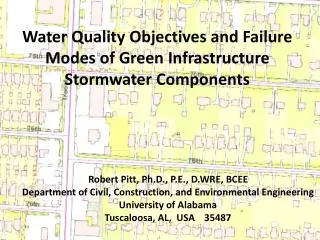
Stormwater Infrastructurefor Water Quality Management Dr. Larry A. Roesner, P.E. CE 394K.2 Surface Water Hydrology University of Texas, Austin April 8, 1999
The Next Generation of UrbanStorm Water Management Urban Runoff Quality Management Practices Larry Roesner, Ph.D., P.E. Camp Dresser & McKee
Receiving Water The Urban Stormwater Problem Flow Quality Regulated by Local Agencies Regulated Principally by EPA & TNRCC
Flow Rate Return Period, yrs Increasing Imperviousness Increases Runoff
Stormflow Impacts • 100 year peak flow increases 2 X • 15 year peak flow increases 3 X • 2 year peak flow increases 57 X (Denver) • 2-yr peak flow occurs • 3 X per year (residential development) • 6 X per year (commercial development)
The STORM Model(Storage Treatment Overflow Runoff Model) Precipitation Wet-Weather Storage Runoff Q=CIA Treatment Overflow
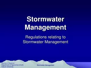
100 90 50% Impervious 50 Percent Capture of Annual Runoff 100% Impervious 0.5 20 0 Treatment Volume Required, inches 1.0 Typical Capture Curves The Design Storm
So What’s the Problem • BMPs target the control of the quality of runoff • Conventional drainage facilities control downstream flooding • Neither of these activities has as its objective protection of the aquatic environment - If it occurs, it is incidental
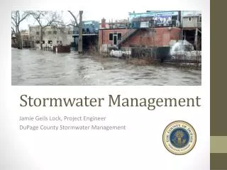
Flow Rate Frequency Curve with Flood & Water Quality Controls Return Period, yrs Stormwater Mgmt Must Address the Entire Flow Frequency Curve
The Fact Is: Simply reducing pollutants in the runoff to the Maximum Extent Practicable will probably not result in significant improvement to the ecological condition of the receiving waters Flow management is also required
Urban Runoff Hydrology The Design Storm 85 percent of the storms in east Texas are less than 1 inch of rainfall 85 percent of the storms in west Texas are less than 0.65 inches Small storms account for most of the runoff and are affected most by urbanization.
Maximized Water Quality Capture Volume The Design Storm Po= a C PA where: Po = Maximized Water Quality Capture Volume (in.) a = Capture Volume Coefficient C = Watershed Runoff Coefficient PA= Mean Storm Precipitation Volume (in.)
Po= a C PA a = 1.3 - 1.6 for 85% capture of annual runoff PA = 0.6 inches in east Texas (wet) = 0.4 inches in west Texas (dry) Po (wet) = 0.12 - 0.14 inches (residential, C=0.15) = 0.70 - 0.86 inches (commercial, C=0.9) Po (dry) = 0.08 - 0.10 inches (residential, C=0.15) = 0.50 - 0.58 inches (commercial, C=0.9) The Design Storm Maximized Volume for Texas
The Stormwater Treatment Train Pollution Prevention • Public Education • Spill Prevention • Used Oil Recycling • Lawn Chemical Mgmt Source Controls • Filter Strips • Swales • Modular Pavement • Infiltration Trenches Treatment Controls • Extended Detention • Retention Ponds • Wetlands
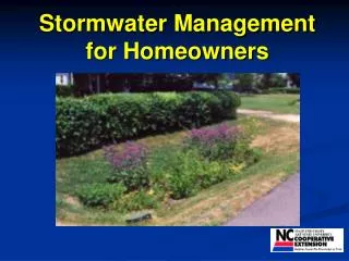
Minimize Directly Connected Impervious Area • Drain Hard Lot Surfaces onto Pervious Areas • Use Modular Pavement where Feasible • Drains Streets to Swales
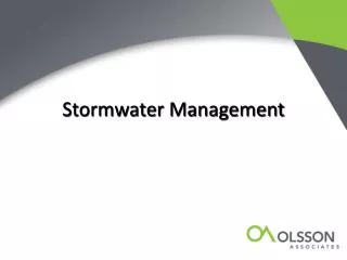
Lot/Site Drainage Depressed Grassed Area Modular Pavement Grassed Parking Area Reinforced with Geotextile Fabric
Lot/Site Drainage Percolation Trench
Basic Design CriteriaPercolation Trench • Seasonal High groundwater or bedrock more than 4 ft below trench bottom • Do not locate in fill material or recompacted soils • Soil should be type A or B with minimum hydraulic conductivity of 6.5 x 105 ft/sec • Po based on lot size and %I
Design Criteria Swales • Provide 1-2% slope • Max V < 1 ft/sec • Max bottom width, 8 ft • Min bottom width, 2 ft • Minimum length 100 ft • Maximum water height for maximized storm • than 1/2 the height of standing vegetation • Po sized for road runoff plus the portion of • maximized storm not captured on building site
Design CriteriaInfiltration Basins • Seasonal groundwater or bedrock > 4 ft below basin bottom • Do not locate on fill or compacted soils • Soil must be type A or B with saturated surface infiltration rate > 0.3 in/hr • Size to drain Po in 12 hour • Use point system in book for rating suitability of a site
Extended DetentionDesign Criteria • Size to detain Po for 12 to 24 hours, then add 20% for sediment storage • Use two stage design (empty less than 50% of volume in first 1/3 of detention time • Sediment forebay recommended • Clogging outlets are most common failure • Emergency spillway • Sideslopes 1:4
Detention with FiltrationDesign Criteria • Capture Po or 1/2 inch of runoff • from impervious area • 24 - 40 hour drawdown time • Minimum sand bed = 18 inches • Seal bottom of filter chamber • Underdrain the sand filter • Provide smooth flow transition from presedi- • mentation chamber to filter chamber
Retention - Design Criteria • Design by one of two methods • - Solids-settling theory • - Lake eutrophication theory • Both facilities are larger than • an extended detention basin • for the same drainage area • For biochemical design, size to • hold runoff from wettest two • weeks for 14 days • Design as regional facilities • as landscape amenity
Constructed WetlandDesign Criteria • Use same guidelines as • biological retention, but • detention time is 14 days • during wettest month • Open water is less that 50% • of total facility surface area • Use a wetland biologist for • developing planting program
The Joint ASCE/WEF Manual of Practice Pragmatic Broadly Based (1998)
Targeting Highway Runoff (1997)
Summary • Design for the small storm • Minimize Directly Connected Impervious Area • Use the treatment train concept • Design outlet controls as multi-stage to reproduce natural flow frequency curve