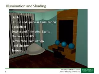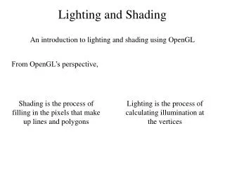
Light and shading
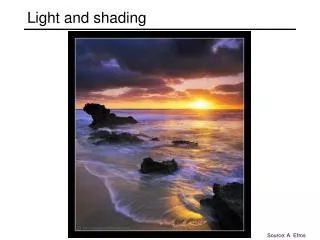
Light and shading. Source: A. Efros. Image formation. What determines the brightness of an image pixel?. Light source properties. Surface shape and orientation. Sensor characteristics. Exposure. Surface reflectance properties. Optics. Slide by L. Fei-Fei.

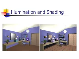
Light and shading
E N D
Presentation Transcript
Light and shading Source: A. Efros
Image formation • What determines the brightness of an image pixel? Light sourceproperties Surface shape and orientation Sensor characteristics Exposure Surface reflectanceproperties Optics Slide by L. Fei-Fei
Fundamental radiometric relation • L: Radiance emitted from P toward P’ • Energy carried by a ray (Watts per sq. meter per steradian) • E: Irradiance falling on P’ from the lens • Energy arriving at a surface (Watts per sq. meter) P α d P’ f z What is the relationship between E and L? Szeliski 2.2.3
Fundamental radiometric relation • Image irradiance is linearly related to scene radiance • Irradiance is proportional to the area of the lens and inversely proportional to the squared distance between the lens and the image plane • The irradiance falls off as the angle between the viewing ray and the optical axis increases P α d P’ f z Szeliski 2.2.3
Fundamental radiometric relation • Application: • S. B. Kang and R. Weiss, Can we calibrate a camera using an image of a flat, textureless Lambertian surface? ECCV 2000.
From light rays to pixel values • Camera response function: the mapping f from irradiance to pixel values • Useful if we want to estimate material properties • Enables us to create high dynamic range images • For more info: P. E. Debevec and J. Malik, Recovering High Dynamic Range Radiance Maps from Photographs,SIGGRAPH 97
The interaction of light and surfaces • What happens when a light ray hits a point on an object? • Some of the light gets absorbed • converted to other forms of energy (e.g., heat) • Some gets transmitted through the object • possibly bent, through refraction • or scattered inside the object (subsurface scattering) • Some gets reflected • possibly in multiple directions at once • Really complicated things can happen • fluorescence • Bidirectional reflectance distribution function (BRDF) • How bright a surface appears when viewed from one direction when light falls on it from another • Definition: ratio of the radiance in the emitted direction to irradiance in the incident direction Source: Steve Seitz
Diffuse reflection • Light is reflected equally in all directions • Dull, matte surfaces like chalk or latex paint • Microfacets scatter incoming light randomly • Effect is that light is reflected equally in all directions • Brightness of the surface depends on the incidence of illumination darker brighter
Diffuse reflection: Lambert’s law N S θ B: radiosity (total power leaving the surface per unit area) ρ: albedo (fraction of incident irradiance reflected by the surface) N: unit normal S: source vector (magnitude proportional to intensity of the source)
Specular reflection • Radiation arriving along a source direction leaves along the specular direction (source direction reflected about normal) • Some fraction is absorbed, some reflected • On real surfaces, energy usually goes into a lobe of directions • Phong model: reflected energy falls of with • Lambertian + specular model: sum of diffuse and specular term
Moving the light source Changing the exponent Specular reflection
Photometric stereo (shape from shading) • Can we reconstruct the shape of an object based on shading cues? Luca dellaRobbia,Cantoria, 1438
S2 S1 ??? Photometric stereo • Assume: • A Lambertian object • A local shading model (each point on a surface receives light only from sources visible at that point) • A set of known light source directions • A set of pictures of an object, obtained in exactly the same camera/object configuration but using different sources • Orthographic projection • Goal: reconstruct object shape and albedo Sn F&P 2nd ed., sec. 2.2.4
Surface model: Monge patch F&P 2nd ed., sec. 2.2.4
Image model • Known: source vectors Sjand pixel values Ij(x,y) • Unknown: surface normal N(x,y) and albedo ρ(x,y) • Assume that the response function of the camera is a linear scaling by a factor of k • Lambert’s law: F&P 2nd ed., sec. 2.2.4
(n × 1) (n × 3) (3× 1) known known unknown Least squares problem • Obtain least-squares solution for g(x,y) (which we defined asN(x,y) (x,y)) • Since N(x,y) is the unit normal, (x,y) is given by the magnitude of g(x,y) • Finally, N(x,y) = g(x,y) / (x,y) • For each pixel, set up a linear system: F&P 2nd ed., sec. 2.2.4
Example Recovered albedo Recovered normal field F&P 2nd ed., sec. 2.2.4
Recall the surface is written as This means the normal has the form: If we write the estimated vector gas Then we obtain values for the partial derivatives of the surface: Recovering a surface from normals F&P 2nd ed., sec. 2.2.4
Integrability: for the surface f to exist, the mixed second partial derivatives must be equal: We can now recover the surface height at any point by integration along some path, e.g. Recovering a surface from normals (for robustness, should take integrals over many different paths and average the results) (in practice, they should at least be similar) F&P 2nd ed., sec. 2.2.4
Surface recovered by integration F&P 2nd ed., sec. 2.2.4
Assignment 1 Input … Estimated albedo Integrated height map Estimated normals x y z
Limitations • Orthographic camera model • Simplistic reflectance and lighting model • No shadows • No interreflections • No missing data • Integration is tricky
Finding the direction of the light source I(x,y) = N(x,y) ·S(x,y) + A Full 3D case: N S For points on the occluding contour: P. Nillius and J.-O. Eklundh, “Automatic estimation of the projected light source direction,” CVPR 2001
Finding the direction of the light source P. Nillius and J.-O. Eklundh, “Automatic estimation of the projected light source direction,” CVPR 2001
Application: Detecting composite photos Real photo Fake photo M. K. Johnson and H. Farid, Exposing Digital Forgeries by Detecting Inconsistencies in Lighting, ACM Multimedia and Security Workshop, 2005.