Download

1 / 21
230 likes | 298 Views
Learn about diesel combustion, injector pumps, engine components, and exhaust treatment in diesel engines. Explore fuel injection systems, turbochargers, glow plugs, and more.

E N D
chapter16 Diesel EngineOperation
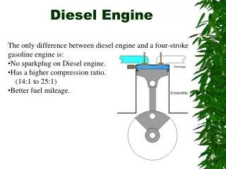
FIGURE 16.1 Diesel combustion occurs when fuel is injected into the hot, highly compressed air in the cylinder.
FIGURE 16.2 A typical injector pump type of automotive diesel fuel–injection system.
FIGURE 16.3 A Cummins diesel engine as found in a Dodge pickup truck. A high-pressure pump (up to 30,000 PSI) is used to supply diesel fuel to this common rail, which has tubes running to each injector. Note the thick cylinder walls and heavy duty construction.
FIGURE 16.4 A rod/piston assembly from a 5.9 liter Cummins diesel engine used in a Dodge pickup truck.
FIGURE 16.5 An indirect injection diesel engine uses a pre-chamber and a glow plug.
FIGURE 16.6 A direct injection diesel engine injects the fuel directly into the combustion chamber. Many designs do not use a glow plug.
FIGURE 16.7 A fuel filter attached to the frame rail on a Ford pickup truck equipped with a diesel engine. When the “water in fuel” warning lamp comes on, the water that is trapped in the filter-water separator assembly can be drained from the unit.
FIGURE 16.8 A typical distributor-type diesel injection pump showing the pump, lines, and fuel filter.
FIGURE 16.9 A schematic of Standadyne diesel fuel–injection pump assembly showing all of the related components.
FIGURE 16.10 Overview of a computer-controlled high-pressure common rail V-8 diesel engine.
FIGURE 16.11 A HEUI injector from a Ford Power Stroke diesel engine. The O-ring grooves indicate the location of the O-rings that seal the fuel section of the injector from coolant and from the engine oil.
FIGURE 16.12 Typical computer-controlled diesel engine fuel injectors.
FIGURE 16.13 A Duramax injector showing all the internal parts.
FIGURE 16.14 A glow plug assortment showing the various types and sizes of glow plugs used. Always use the specified glow plugs.
FIGURE 16.15 A Cummins diesel turbocharger is used to increase the power and torque of the engine.
FIGURE 16.16 An air charge cooler is used to cool the compressed air.
FIGURE 16.17 After treatment of diesel exhaust is handled by the DOC and DPF.
FIGURE 16.18 The soot is trapped in the passages of the DPF. The exhaust has to flow through the sides of the trap and exit.
FIGURE 16.19 Diesel exhaust fluid costs $3 to $4 a gallon and is housed in a separate container that holds from 5 to 10 gallons, or enough to last until the next scheduled oil change in most diesel vehicles that use SCR.
FIGURE 16.20 Urea (diesel exhaust fluid) injection is used to reduce NOx exhaust emissions. It is injected after the diesel oxidation catalyst (DOC) and before the diesel particulate filter (DPF) on this 6.7 liter Ford diesel engine.