Chapter 2 Assembly Language Programming
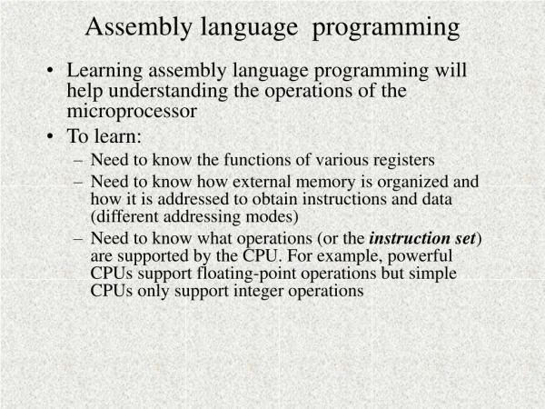
Chapter 2 Assembly Language Programming. Assembly Language Programming. 왜 Assembly Language Programming 을 배워야 하나 ? 프로세서의 동작 이해에 필요 하다 . Programmable Digital System 설계에 필요한 기본 기술 이해 프로그램 오류 ( 알고리즘 또는 Coding 상의 문제 ) 해결에 필요 Higher-level Language 가 지원하지 못하는 Hardware 기능 구현
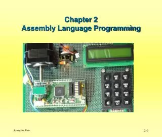

Chapter 2 Assembly Language Programming
E N D
Presentation Transcript
Assembly Language Programming • 왜 Assembly Language Programming 을 배워야 하나? • 프로세서의 동작 이해에 필요 하다. • Programmable Digital System 설계에 필요한 기본 기술 이해 • 프로그램 오류(알고리즘 또는 Coding 상의 문제) 해결에 필요 • Higher-level Language 가 지원하지 못하는 Hardware 기능 구현 • Time-critical 한 Routine의 작성 • Assembly Language 의 특징 • Assembler Instructions은 1대 1로 MachineInstruction에 대응 한다. • uP의 성능을 100% 구현 할 수 있다. • 가장 효율적인 프로기램구현이 가능 하다. • 실행 속도 • 프로그램 Code 길이 • 배우기쉽다.
Assembly Language Programming • Instruction Set 란? • 프로세서의 명령 실행 주기 동안에 실행되는 Code set를 말한다. • Binary Instructions • 명령어에서 Binary pattern 111011000001100(0xEA0A) 의 의미는 • R16 0xAA (LDI R16, 0xAA) 의 의미 이다. • 위 Binary Instruction은 프로세서에게는 효과적인 명령 이지만 인간이 이해하기에는 너무불편하여 보다 효과적인 표시 방법이 필요 하여, • 16진법과 8진법을 이용 하여 에서 Binary pattern 을 표시 한다. • 그러나, 16진법과 8진법도 인간이 프로세서의 동작을 이해하기에 부족 하기 때문에 Assembly Language를 사용 한다.
Assembly Language • 인간이 좀더 쉽게 프로세서의 명령을 이해할 수 있도록 이해하기 쉬운 심볼을 사용한 프로그래밍 언어 이다. • 예) • Instruction Mnemonic Rg/Memory Hexadecimal Equivalent • ldi R16, 0xAA EA0A • mov R0, R16 2E00 • ldi R16, 0x55 E505 • mov R2, R16 2E20 • Assembler • 그러나 Assembly Language 는프로세서가 직접 실행할 수 없기 때문에 Assembly Language 로 작성된 프로그램을 Binary Instruction 으로 변환 하는 프로그램이 필요 하게 되고, 이 프로그램이 Assembler 이다.
Microcontroller • Assembly language Development Process ( 그림 예에서 Source Code는 다른 프로세서의 예 임) Loader Assembler Processor Source Code ; I/O Port Init clrAC0 sts PORTF, AC0 out DDRD, AC0 serAC0 out PORTD, AC0 stsDDRF, AC0 Object Code 00004b 2700 00004c 9300 0062 00004e bb01 00004f ef0f 000050 bb02 000051 9300 0061 RAM ROM 2700 9300 0062 bb01 Ef0f bb02 9300 0061 I/O Port External Device
AVR128A Processor • Architectural Overview : Block Diagram of the AVR Architecture
Architectural Overview • Harvard architecture • Program 과data를 위한 Memory와 Bus가 분리되어 있다. • Register file : 32 x 8-bit general purpose working registers • 3개의 16-bit indirect address register pointers. • ALU supports arithmetic and logic operations • Registers Registers fun Registers • Registers Registers fun Constant • Program Flash memory space 는 • Boot Program section 과 • Application Program section 2가지로 구성 된다. • I/O memory space contains 64 addresses : $20 - $5F • ATmega128A 는 Extended I/O space($60 - $FF in SRAM)를 갖는다. 오직 ST/STS/STD and LD/LDS/LDD 명령만 사용 가능 함.
ALU – Arithmetic Logic Unit • High-performance AVR ALU operation • 32 개의 general purpose working registers와 직접 연결 되어 있다. • Single clock cycle arithmetic operations • Registers Registers fun Registers • Registers Registers fun Constant • Three main categories ALU operations • Arithmetic, Logical, and Bit-functions • Powerful multiplier • Signed/unsigned multiplication and fractional format
Status Register • 최근에 실행된 Arithmetic instruction 결과에 대한 정보를 표시한다. • 이 정보는 Program 흐름을 바꾸는 Conditional Operations에 사용 할 수 있다. • 모든 ALU 연산에 의하여 Status Rg 가 Update 된다. • SREG - AVR Status Register • Bit 7 – I: Global Interrupt Enable Bit • Bit 6 – T: Bit Copy Storage • Bit Copy instructions BLD (Bit LoaD) 과 BST (Bit STore) 에서 T-bit 가 source 또는 destination 으로 사용 된다.
Bit 5 – H: Half Carry Flag : Half carry는 BCD arithmetic에서 이용 된다. • Bit 4 – S: Sign Bit, S = N ⊕ V • Bit 3 – V: Two’s Complement Overflow Flag • Bit 2 – N: Negative Flag • Bit 1 – Z: Zero Flag • Bit 0 – C: Carry Flag • Register File의 Address Map • Data memoryspace 의 첫 32($20) 번지에 mapping 된다.
AVR General Purpose Register File Rg0 – Rg15 Rg16 – Rg31
X-register, Y-register, and Z-register • Registers R26:R31은 일반 Rg로의 기능 이외에 Data Space 에서 Indirect addressing을 위한 16-bit address pointers 로서의 기능을 갖는다.
Index Rg 이용 예 • 1000 번지 부터 1099 번지 까지 100Byte를 2000 번지 부터 저장하라. • Index Rg 가 없는 경우의 예 • (2000) (1000) • (2001) (1001) • (2002) (1002) • - - - - • - - - - • (2099) (1099)
Index Rg 이용 예 • 1000 번지 부터 1099 번지 까지 100Byte를 2000 번지 부터 저장하라. • Index Rg 와 CounterRg가 있는 경우의 예 • Start : • Index Rg1 1000 • Index Rg2 2000 • Counter Rg 100 • Loop : • (Index Rg2 ) (Index Rg1) • Index Rg1 Index Rg1 + 1 • Index Rg2 Index Rg2 + 1 • Counter Rg Counter Rg - 1 • If (Counter Rg != 0 ) goto Loop • Done:
AVR Memory Space • Data Memory Map • Working Registers • Includes X, Y, and Z registers. • I/O Register Space • Includes “named” registers • SRAM – Data Space • Runtime Variables and Data • Stack space • Program Flash Memory Map • Program Flash Memory • Vectors, Code, and (Unchangeable) Constant Data. • Boot Program Flash Memory • EEPROM space • For non-volatile but alterable data
In-System Reprogrammable Flash Program Memory • 128K bytes On-chip In-System • All AVR instructions are 16 or 32 bits wide. • Flash is organized as 64K x 16 • Divided into two sections • Boot Program section and • Application Program section.
SRAM Data Memory Memory Configurations • Tmega128A Normal Mode • Register file : First 32($0-$19) locations address • Standard I/O memory : Next 64($20-$5f) location • Extended I/O memory : Next 160($60-$ff) locations • Internal data SRAM : Next 4096 locations address
EEPROM Data Memory • ATmega128A • 4K bytes 의 Data EEPROM memory • Separate data space • Single bytes read, written 가가능 함. • EEPROM access registers are accessible in the I/O space • EEPROM is read, the CPU is halted for four clock cycles before the next instruction is executed • EEPROM is written, the CPU is halted for two clock cycles before the next instruction is executed
I/O Memory • ATmega128A • ATmega128A의 모든 I/O 와주변 장치는 I/O Space에할당 되어 있다. • I/O Space에할당된 모든 I/O와 주변 장치의 32개의 Register와 Data Transfer 가 가능 하다. • IN, OUT 명령은 I/O addresses $00 - $3F에 할당된 I/O와 주변 장치에 사용 한다. • Data Space에 있는 I/O Registers($60-$FF)는 LD 와 ST 명령을 사용 한다. • I/O Port의 실제 번지는 32개의 일반 Register에 할당된 $0-$19($20) 번지 값을더 한 값이 된다. 참고자료: ATmega128_doc8151.pdf
AVR Instruction Set Overview • The AVR instruction set is divided into: • ARITHMETIC AND LOGIC INSTRUCTIONS • Branch instructions • DATA TRANSFER INSTRUCTIONS • BIT AND BIT-TEST INSTRUCTIONS • MCU CONTROL INSTRUCTIONS
일반적인 uP에서 Registers의 종류와 역활 • Data Rg • 연산 및 자료 처리에 필요한 Data를 저장함 • Index Rg • Operand 의 주소를 저장( Pointing ) 함. • Stack Pointer • Last-In-First-Out : Stack Operation • First-In-First-Out : Buffed I/O 에 유용 • Program Counter • 다음에 실행할 명령어의 번지를 저장함. • Status Rg • 연산 결과 상태를 표시하는 Flag 를 저장함.
Stack Pointer • Stack은 LIFO(LastIn First Out) 알고리즘을수행 한다. • Stack의 이용 분야 • Temporary data의 저장 • Local variables의 저장 • Interrupts 과 Subroutine calls 후 Return addresses의 저장 • Stack은 Stack 영역이필요 할 경우 Stack memory의 Higher memory locations 로 부터 Lower memory locations으로확장된다. • Stack Pointer Register 는항상 Stack의 Top위치를 Pointing 한다. • Stack Pointer instructions
SPH and SPL - Stack Pointer High and Low Register • AVR Stack Pointer 는 I/O space 내에 Two 8-bit registers로실현된다. • Stack 영역을 작게 요구되는 기종에서는 SPL(8-bit)만 이용 된다.
Subroutines and the Stack • Last in First Out (LIFO) • 사용 예 : Stack Operation • First in First Out (FIFO) • 사용 예 : I/O Buffer 등 • Stack의 사용 예 • Subroutine 의 Return Address 저장 • Local variable 영역 확보 • Parameter Passing : 상위 계층 프로그램 모듈과 하위 모듈 사이에 Parameter Passing • Subroutine 내에서 사용하는 Rg의 보호를 위한 임시 저장 장치로 사용
Subroutines and the Stack • push Operation 예 : push Rg • (SP) ← Rg • SP ← SP - 1 • Pull Operation 예 : pull Rg • SP ← SP + 1 • Rg ← (SP)
Subroutines and the Stack • Subroutine • 일반 프로세서에서의 Subroutine • Call sub • (SP) PC • SP SP-- • PC Subroutine의 시작 번지 • Return • SP SP ++ • PC (SP) 주:여기에서 ++, -- 의의미는 다음 번지, 이전 번지의 의미 임.
2.2.9 Subroutines and the Stack • push Operation • ldi R16, 0xAA • push R16 Push Operation 실행전 실행 후
2.2.9 Subroutines and the Stack • pop Operation • pop R16 Pop Operation 실행전 실행 후
일반적인 Addressing Mode • Inherent Addressing Mode • Operand Field 를 갖지 않는다. • Immediate Addressing Mode • Operand Field 에 상수 값이 직접 주어진다. • Direct Addressing Mode • Operand Field에 실제 Address 가 온다. • Indirect Addressing Mode • Operand Field에 실제 Address가 저장된 주소가 온다. • Relative Addressing Mode • PC 또는 Index Rg 를 기준으로한 상대번지가 온다.
AVR uP의 Addressing Mode • Register Direct, with 1 and 2 registers • I/O Direct • Data Direct • Data Indirect • with pre-decrement • with post-increment • Code Memory Addressing
Register Direct: 1 Register Example: inc R16 clr R22
Register Direct: 2 Register Rd: R0-R31 or R16-R31 ( Depending on instruction) Rr: R0-R31 Example: add R16,R17 cp R22,R5 mov R0,R1
I/O Direct Example: in R16,PIND out PORTC,R16
Data Direct Example: sts 0x1000,R16
Data Indirect Example: ld R16, Y st Z, R16
Data Indirect r/w Displacement Example: ldd R16, Y+0x10 std Z+0x20, R16 +
Data Indirect : Pre-Decrement Example: ld R16, -Z st-Z, R16 +
Data Indirect : Post-Increment Example: ld R16, Z+ stZ+, R16 +
Program Memory Addressing Example: lpm R30, Z+
Indirect Program Memory Addressing Z Rg를 Index Rg로 사용 한다. Example: ijmp icall
Relative Program Addressing Example: rjmp rcall +