Download
1 / 13
130 likes | 269 Views
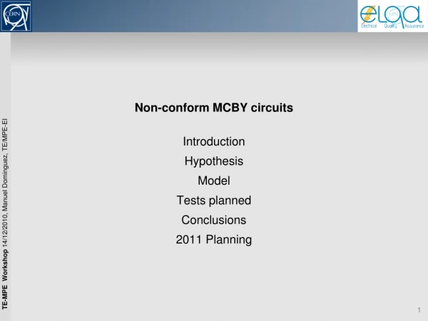
Non-conform MCBY circuits. Introduction Hypothesis Model Tests planned Conclusions 2011 Planning. Introduction. We have found an unexpected behavior in some 120A circuits (individual powered correctors).

E N D
Non-conform MCBY circuits Introduction Hypothesis Model Tests planned Conclusions 2011 Planning
Introduction • We have found an unexpected behavior in some 120A circuits (individual powered correctors). • 6 MCBY & 3 MCBC magnets are quenching when ramping up/down, usually when going to 0A. • List of circuits: • Several tests have been made in 2008, 2009 to discard power converters, cryo conditions… • RCBCV8.L1B2 • RCBYHS4.L5B1 • RCBCH7.L8B1 • RCBYH4.L2B2 • RCBYHS5.R8B1 • RCBCV7.L2B2 • RCBYH4.R8B1 • RCBYV5.L4B2 • RCBYHS4.R2B1
Introduction • Symptoms: • The magnets cannot stand the nominal di/dt • We can observe a bump in themeasured current when the magnet quenches • No appreciable degradation in the quenches • Power converter instability problem, dueto different TF of the magnets.This was solved by EPC group addinga virtual resistance of 70 Ohm in parallelto the magnet in the PC model.
Hypothesis • The first idea, pointed by Glyn Kirby, was a kind of transformer effect. • That could happen when a loop is shorted in the middle of the coil. • We will have N1=29 and N2=1. The change in flux in the large inductance will produce a high current in the lower inductance, that will quench the loop in short. • This is a detail of the presumable place for the short.
Model • A model of the MCBY with the short is done in Matlab. It’s based on the work started by Bernhard Auchmann. • The circuit is analytically resolved and simulated in Matlab, adding the thermodynamic calculations.
MCBY vs Model (replica of a real quench) Real quench. PM file: 091124-50723.820 • Simulation in Matlab, with the same ramps and times. • Similar results. • Differences: • Magnitude of the bump • Current in the quench
MCBY vs Model (replica of a real quench) • Explanation of the quench, seeing what is happening in the loop in short. Imax
Temperatures & Voltages • The simulations are done assuming the adiabatic case, so we are in the worst case, to be sure that the magnet will besafe. Currents Temperatures Voltages (in the magnet) Voltage in the PC
Tests planned • To validate the model and fix some parameters affecting the simulations, we need to fake a short and see what is happening in this turn. • Test proposals: • Magnet: Using a spare one (HCMCBYB001-TE000043). It’s ready and stored in building 927. • Place for the tests: Block 4 (SM18) • Instrumentation: both apertures with Vtaps in all turns • Faking a short in one aperture. This is done with a stainless steel piece soldered between two turns, with an Rs=0.0015 Ohm.
Tests planned • Examples of the current cycles planned:
Conclusions • Main parameters affecting the results of the simulation are: • modeling and value of the short resistance • quench velocity propagation • exact current that makes the loop in short quench • We will know them empirically, measured in the tests, to have better and more realistic simulations. Once these parameters are fixed, we should be able to reproduce the measured voltages and currents. • We will be able to know the maximum voltage developed inside an MCBY coil during a quench, in a healthy and in an sick magnet. • Voltage withstand could be re-defined for these magnets, as it was not fully measured.
2011 Planning • The maximum time length for the tests should be around one week, including installation of the magnet, cooling, tests and warming. • The date is not fixed, we are waiting for the confirmation. • Relative to LHC: • There’s a good margin with the sick MCBY’s and MCBC’s. They are working well within their safety parameters. In fact, some of them are not being used, but the working parameters are changing depending on the optics. • Just taking in account the safe maximum ramp rate (different for each magnet) there shouldn’t be any problems to go to 4 Tev or 4.5 Tev.