Download
1 / 3
30 likes | 43 Views
The various types of stepper motors are Unipolar stepper motor, bipolar stepper motor, micro stepper motor and stepper driver. Applications are welding, textile machines and printing presses

E N D
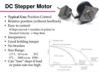
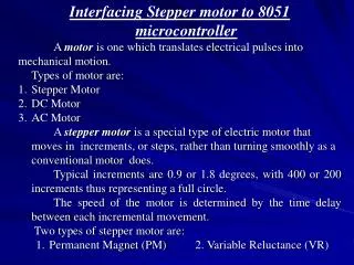
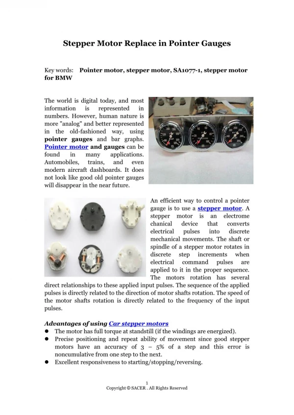
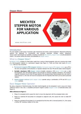
Stepper Motor Introduction Pro-Lite supplies a wide range of precision opto-mechanical and motion control equipment. Motorized positioning systems are deployed to conveniently and precisely Various motor technologies are available, including conventional DC motors, stepper motors as well piezoelectric motors. This article reviews the theory and attributes of stepper motors. What is a Stepper Motor? A stepper motor consists of a fixed stator made from a series of electromagnetic coils and a moving rotor made of a ferromagnetic material or a permanent magnet (see Figure 1). There are three main types of stepper motor that you may encounter: automate complex motion sequences. 1.Permanent magnet (PM) stepper motors:Permanent magnet (PM) stepper motors use a PM in the rotor and operate on the attraction or repulsion between the rotor PM and the stator electromagnets. 2.Variable reluctance (VR) stepper motors:Variable reluctance (VR) stepper motors use a plain ferromagnetic rotor and operate based on the principle of minimum magnetic reluctance. The minimum magnetic reluctance occurs when the gap between the energized stator electromagnet and rotor teeth is at its minimum i.e. the rotor will move to be aligned with the magnetic field which can be used to generate rotation. 3.Hybrid stepper motors: Hybrid stepper motorsoperate using a combination of PM and VR stepper motor methods. Basic Stepper Motor Operation By using a sequence of electrical pulses, the stator electromagnets can be energized in such a way as to induce rotational motion in the rotor. A simplified permanent magnet 2-phase stepper motor is illustrated below (see Figure 2). With reference to Figure 2: 1.Phase A is energised which causes the rotor to move into alignment with the energised stator coils. 2.Phase A is switched off and phase B is energised on adjacent coils, this causes the rotor to rotate 90° clockwise. 3.Phase B is switched off and phase A is re-energised but this time with a reversed polarity (A-), this causes a further 90° clockwise rotation of the rotor.
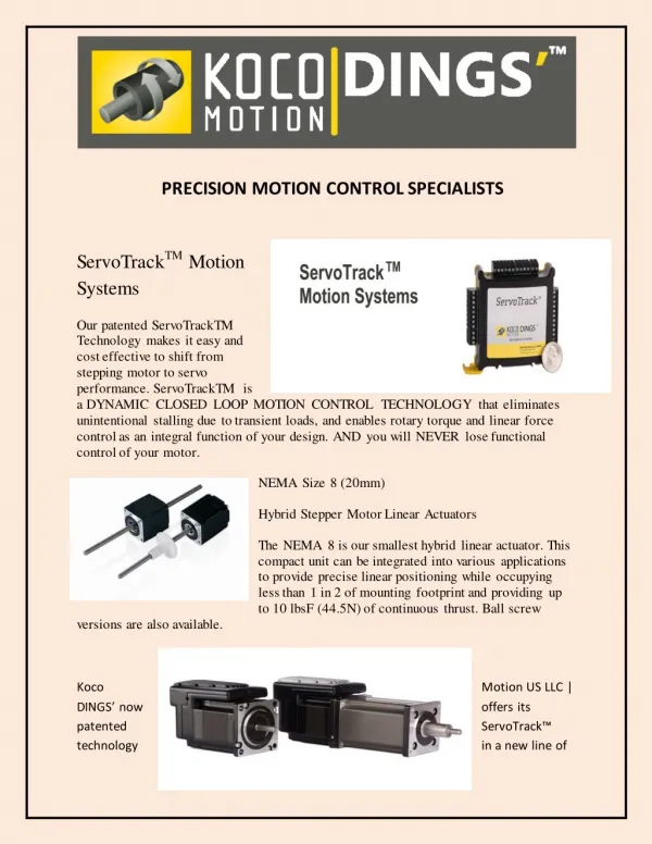
4.Phase A- is switch off and phase B is re-energised but this time with a reversed polarity (B-), this causes a further 90° clockwise rotation of the rotor. Repeating this sequence causes the rotor to continue rotating. For counter clockwise rotation the sequence should be reversed. Each step moves the rotor through a fixed angle, the angle depending on the number of rotor teeth within the motor. A typical full step angle found in a 2-phase stepper motor is 1.8° per step, which means that one full rotation of the rotor will take 200 full steps. Microstepping for Smoother Motion and Increased Precision By varying the amount of current applied to the stator coils it is possible to increase the step resolution of the motor to be finer than the full step angle. This is achieved by delivering two sine wave current signals 90° out of phase to adjacent stator coils. This has the effect of decreasing the current in one coil as it is increased in the adjacent coil, this will cause the rotor position to lie somewhere between the two coils (see Figures 3 & 4). This is known as a microstep and the size of the smallest microstep achievable is dependent on the resolution of the driving electronics used to energise the stator coils. As an example, the LIMES 84N stepper motor linear stage from OWIS uses a stepper motor with 200 full steps per revolution (see Figure 5 for a 3-axis assembly). When used with the OWIS PS 90 position control unit it is possible to divide each full step into a further 256 microsteps. This gives a total of 51,200 microsteps per revolution of the motor or 0.007° per microstep. When converted into linear motion via a precision ball screw, microstepping allows very fine position increments to be made. In addition to improving the precision of the motor there are a number of performance advantages created by microstepping. One key advantage is the reduction of torque ripple, which is often encountered when operating in full step mode. In full step mode the stator coils are either energised with maximum current or switched off, which means that as the rotor moves between each full step position there is a large variation in the available torque. Torque ripple results in rough, unstable motion which leads to noise and unwanted vibrations. Microstepping solves this issue as the stator coil current is applied more gradually, resulting in a smoother transition between steps. Open Loop Operation for Simplified Control Each microstep of a stepper motor corresponds to a small fixed motion increment. In order to reach a certain position, the controller need only count the number of microsteps travelled from a home or reference position. No additional position feedback encoder is required in open loop mode. This results in a more straightforward and less costly motion control solution. Open loop mode also allows the motor to have an excellent response to input drive signals, producing quick start / stop response times. Due to the absence of feedback and servo control in open loop operation, a stepper motor can hold a fixed position with a very high degree of stability without any unwanted servo dither. Similarly, as the stator coils remain energised even when stationary, a high holding torque can be achieved, making stepper motors ideal for step and hold applications. Stepper Motor Disadvantages There are some drawbacks to stepper motors. Primarily the lack of position feedback can lead to situations where the position integrity may be compromised, particularly if used under heavy loads that exceed the torque specification of the motor. High loads can cause unwanted movement or stalling of the motor, which combined with the lack of position feedback, can result in an incorrect position readout. The open loop mode also requires that a position reference be taken if the absolute position is required. This means that homing cycles need to be executed before an application can run. Position information will also be lost if the motor or controller suffers a power failure requiring a fresh homing cycle before the application can resume. If absolute position is critical to an application, then using a motion control solution with absolute position feedback would be more suitable. Whilst one of the advantages of stepper motors is their ability to hold a fixed position, this mode of operation can also have a downside. The stator coils remain energised when stationary or when operating at low speeds, which means that excess heat is generated. Without effective heat removal this excess heat can become a problem for sensitive applications. This can be overcome by carefully controlling the phase currents supplied to the motor but at the expense of holding torque. In these situations, it may be better to consider a DC servo motor as an alternative. At low speeds and at low rates of acceleration, stepper motors are often the preferred choice. However, at higher rotational speeds the torque that can be generated by a stepper motor reduces. The drive signals sent to the stator coils generate a magnetic field within the coils. it is this magnetic field that induces a motion in the rotor. When operating at low speeds there is enough time for the current flowing through the coil to induce a strong magnetic field, allowing the motor to provide its fully rated torque performance. If the speed of rotation is increased there is less time for the coils to fully energise in response to a drive signal. This results in a reduced amount of torque
available to the motor. For applications which require high speed with high torque then a servo motor would be able to offer improved performance over a stepper motor. Summary Stepper motors offer a very effective motion control solution, often at lower cost than an equivalent servo motor. They are also highly reliable, containing no contact bushes within the motor, improving the motor lifetime, and making them an ideal solution for OEM and industrial applications. The ability of a stepper motor to operate in microstep mode can provide a very high degree of precision that is frequently required in many photonics motion control applications. The microstepping ability also gives a stepper motor a wide velocity range and can provide stable motion even at very low velocities. The simplified open loop operation of stepper motors is also a major advantage, providing cost and time saving benefits to the end user. A large number of sizes and power options are readily available, which allows stepper motors to be used in a wide range of precision motion control applications, including: Image scanning Step and hold positioning and measurement Camera and sensor positioning Lens and mirror positioning 2D and 3D printing applications Applications that require low acceleration and a high holding torque