Interfacing Stepper motor to 8051 microcontroller
Interfacing Stepper motor to 8051 microcontroller A motor is one which translates electrical pulses into mechanical motion. Types of motor are: Stepper Motor DC Motor AC Motor

Interfacing Stepper motor to 8051 microcontroller
E N D
Presentation Transcript
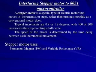
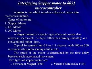
Interfacing Stepper motor to 8051 microcontroller • A motor is one which translates electrical pulses into • mechanical motion. • Types of motor are: • Stepper Motor • DC Motor • AC Motor • A stepper motor is a special type of electric motor that moves in increments, or steps, rather than turning smoothly as a conventional motor does. • Typical increments are 0.9 or 1.8 degrees, with 400 or 200 increments thus representing a full circle. • The speed of the motor is determined by the time delay between each incremental movement. • Two types of stepper motor are: • Permanent Magnet (PM) 2. Variable Reluctance (VR)
Motor Moves Each Time a Pulse is Received • Can Control Movement (Direction and Amount) Easily • Can Force Motor to Hold Position Against an Opposing Force
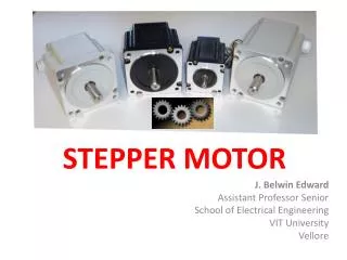
Construction • Permanent Magnet Rotor • Also Called the Shaft • Stator • Surrounds the Shaft • Usually Four Stator Windings Paired with Center-Tapped Common • Known as Four-Phase or Unipolar Stepper Motor
Construction (con’t) • Center Tapped Common
Moving the Rotor Unstable Stable Rotor will ALWAYS seek a stable position.
Single-Coil Excitation - Each successive coil is energised in turn.
Two-Coil Excitation - Each successive pair of adjacent coils is energised in turn.
Interleaving the two sequences will cause the motor to half-step 8 step sequence = normal 4 step + wave drive 4 step.
Single-Coil Excitation Two-Coil Excitation Interleaved Single- and Two-Coil Excitation Half-Stepping
How Far Does It Move? • Step Angle • Arc Through Which Motor Turns With ONE Step Change of the Windings • Varies With Model of Stepper Motor (Depending on the number of teeth on stator and rotor) • Normally in Degrees • Step angle = 360/No. of Steps per Revolution • Commonly available no. of steps per revolution are 500, 200, 180, 144, 72, 48, 24
How Fast? Revolutions per Minute (RPM) The top electromagnet (1) is turned on, attracting the nearest teeth of a gear-shaped iron rotor. With the teeth aligned to electromagnet 1, they will be slightly offset from electromagnet 2. The top electromagnet (1) is turned off, and the right electromagnet (2) is energized, pulling the nearest teeth slightly to the right. This results in a rotation of 3.6° (1.8’) in this example. The left electromagnet (4) is enabled, rotating again by 3.6° (1.8’). When the top electromagnet (1) is again enabled, the teeth in the sprocket will have rotated by one tooth position; since there are 25(50) teeth, it will take 100(200) steps to make a full rotation in this example. The bottom Electromagnet (3) is energized; another 3.6° (1.8’) rotation occurs.
Drivers • May Need a Driver Circuit • Same Problem as Relays – May Draw Too Much Current • Types • Transistor Drivers • Usually a Darlington Pair • Darlington Arrays • Can Build It Yourself
Applications: • Used in • In instrumentation such as watches, clocks, etc. • Computer peripherals such as card readers, teleprinters, teletypes, dot matrix printers, etc. • Robotics
//Program for stepper motor interface #include <REG51xD2.H> void delay (unsigned int x) /* Delay Routine */ { for(;x>0;x--); return; } void main ( ) { unsigned char Val, i; P0=0x00; Val = 0x11; for (i=0;i<4;i++) { P0 = Val; Val = Val<<1; /* Val= Val>>1; for clockwise direction*/ delay (500); }}
DC Motors • Only One Winding • Two Connections: + and – • Reversing Polarity Reverses Motor • Move Continuously • Cannot Determine Position
Characteristics: • RPM • No Load: Maximum RPM With No Load on Shaft • Given in Data Sheets • Loaded: Actual Maximum When Loaded • Not in Most Data Sheets • Voltage Range • Speed Increases With Voltage on a Given Motor • Current Draw • Data Sheet Rating Is With Nominal Voltage and No Load • Increases With Load • Speed Decreases With Load
Bi-Directional Control • Can Change Polarity With a Little Work • H-Bridge Is Simplest Method • Uses Switches (Relays Will do)
Controlling Speed • Speed Depends On • Load • Voltage • Current • Can Control Power By Changing (Modulating) Width of Pulse to Motor • Wider Pulse Faster Speed • Narrower Pulse Slower Speed • Note: Doesn’t Work With AC Motors • AC Motor Speed Depends on AC Frequency (CPS)
#include<REG51xD2.H> sbit inr=P3ˆ2; //speed increment switch sbit dcr=P3ˆ3; //speed decrement switch main() {unsigned char i=0×80; //i has initial speed value=half speed = 80 H P3=0×ff; //configure P3 to accept switches while(1) {if (!inr) //if increment is pressed {while (!inr); //wait till key is released if (i>10) //if speed is more than minimum i=i-10; //increase the DC motor speed, by decreasing the count } //end of if if (!dcr) //if decrement is pressed {while (!dcr); //wait till key is released if (i<0xf0) //decrease the DC motor speed, by increasing the count } //end of if P0=i; //output the value to port P0 for speed control } } //end of while and main
Hex keypad Placement of keys on port lines Connection of Hex keypad to 8051
#include<reg51xd2.h> #include<intrins.h> #include"lcd.h" unsigned char rows,columns,result; unsigned char temp = 0; void delay() //delay subroutine {unsigned int i; for(i=0;i<=20000;i++);} //display subroutine to convert hex to ASCII and display on LCD void Display() {if(result>0x09) {result += 0x37; //if value is greater than 9, add 37H WriteChar(result);} else {result += 0x30; //if value is between 0 to 9, add 30H WriteChar(result);} } //end of display subroutine
void KeyScan() //Keypad subroutine {again:columns = 0x0e; //make P1.0 low rows = 0x04; //4 rows to check result = 0x0; //Key value starts at ‘0’ next: P1 = columns; //output columns CY = 1; //make CY = 1 for next rotation columns <<= 1; //rotate ‘columns’ left temp = P0; //store in temp temp = (temp & 0x0f); if(temp != 0x0f); //if key pressed {rot: temp>> = 1; if(!CY) {ClrLcd(); //key found return;} else {result += 1; //next column; key value is incremented goto rot;} }
else {result += 0x04; //for next row; 4 is added to key value rows - -; //decrement number of rows if(rows = = 0) goto again; //start from beginning else {goto next; } }} void main() {P0 = 0xff; //make as input port P1 = 0x00; InitLcd(); //initialize LCD WriteString("KEY PRESSED=") while(1) {KeyScan(); //call keypad subroutine WriteString("KEY PRESSED=") Display(); //display the value } }
#include<reg51xd2.H> void delay(unsigned int); main() {unsigned char Flr[9] = {0xff,0x00,0x03,0xff,0x06,0xff,0xff,0xff,0x09}; unsigned char ReqFlr,CurFlr = 0x01,i,j; P0 = 0x00; P0 = 0xf0; while(1) {P1 = 0x0f; ReqFlr = P1|0xf0; while(ReqFlr == 0xff) ReqFlr = P1|0xf0; //Read Request Floor from P1 ReqFlr = ~ ReqFlr; if(CurFlr == ReqFlr) //If request floor is equal to current floor {P0 = Flr[CurFlr]; //Clear Floor Indicator P0 = P0|0xf0; //Enable again continue; //Go up to read again }
else if (CurFlr > ReqFlr) //If current floor is > request floor { i = Flr[CurFlr] - Flr[ReqFlr]; //Get the no of floors to travel j = Flr[CurFlr]; for(; i>0; i- -) //Move the indicator down {P0 = 0x0f0 | j; j- -; delay(25000); }} else //If Current floor is < request floor {i = Flr[ReqFlr] - Flr[CurFlr]; //Get the no of floors to travel j = Flr[CurFlr]; for(; i>0; i- -) //Move the indicator Up {P0=0×f0 | j; j++; delay(25000); }}
CurFlr = ReqFlr; //Update current floor P0 = Flr[CurFlr]; //Clear the request indicator P0 = P0|0xf0; } //end of while } //end of main void delay(unsigned int x) {for(; x>0; x- -);}
The following are the Port connections for 89C51ED2 and ICL7109(ADC) i/p :P0 is connected to data lines of the ADC o/p :P2 lower nible ADC control lines o/p P1.1 ---- relay control . o/p :P2.0 --- LBEN active low o/p :P2.1 --- HBEN active low o/p :P2.2 --- CE active low o/p :P2.3 --- RUN active high o/p :P2.4 --- RELAY active high i/p :P1.0 --- Status of ADC:- ready when low
An electrical transducer is a sensing device using which a physical, mechanical or optical quantity to be measured is transformed into electrical signal (voltage or current) proportional to input. PT100 is a temperature transducer which converts change in temperature to change in resistance. Change in resistance is represented by change in voltage using a resistance bridge. A RTD (Resistance Temperature Detector) is a temperature sensing device whose resistance increases with temperature. Resistance of RTD is calculated by Wheat stone bridge. Vo = VEX( R3/[R3+R4]) – VEX(R2/[R1+R2]) R4 = ((R1(VEX-Vo) - R2 Vo)R3) / (R1 Vo + R2 (VEX + Vo)) If R1=R2=R3=100Ω and bridge ix excited at VEX = 1.8V Then, R4= ((100(1.8-Vo) – 100*Vo)100) / (100*Vo + 100(1.8+Vo)) Analog output of resistance bridge is converted to digital output which is read by 8051 microcntroller, which in-turn controls the power to the heating element. It uses 12-bit dual slope integrating ADC (ICL 7109).
# include <reg51xd2.h> #include "lcd.h" unsigned int Adc; unsigned char Low_adc,High_adc,relay; sbit ce=P2^2, rc=P1^1, LBEN=P2^0, HBEN=P2^1, soc=P2^3; read_adc() {unsigned char status; soc = 1 ; // Start conversion of ADC status = P1; //Read status of ADC while((status & 0x01) != 0x01) {status = P1;} ce = 0; // Enable outputs LBEN = 0; // Activate B1 to B8 outputs Low_adc = P0; // Read lower byte of ADC and place in R0 LBEN = 1; // Deactivate B1 to B8 outputs HBEN = 0; // Activate B9 to B12 and POL, over range outputs High_adc = P0; // Read higher byte of ADC High_adc = High_adc & 0x0F;
HBEN= 1; // deactivate B9 to B12 and POL, over range outputs ce = 1; // Disable outputs soc = 0; // Stop conversion of ADC} main() { float Temp,Vol,Res; unsigned char Temp1,Temp2,Temp3; P0 = 0xFF ; // Make port 0 as input P2 = 0xFF ; // Make port 2 as high now the relay is on. rc = 0 ; // switch OFF relay soc = 0 ; // STOP conversion of ADC while(1) {read_adc(); //Read ADC Adc = High_adc; Adc <<= 8; Adc = Adc | Low_adc; if( (Adc > 0x656) && (relay != 0)) //IF > 0x0656 Switch OFF relay {ClrLcd(); WriteString("RELAY OFF");
rc = 0 ; relay = 0;} else if ( (Adc < 0x656) && (relay!= 1)) //IF less than 0x05B9Switch ON relay { ClrLcd(); WriteString("RELAY ON"); rc = 1 ; relay = 1; } Vol = -((Adc/10)*0.000488); //voltage before amplifier Res =((100*(1.8-Vol)-100*Vol)*100) /(100*Vol +100*(1.8+Vol)); // Resistance Value Res = Res - 100; Temp = Res/ 0.384; Temp1 = Temp; Temp2 = 0x30 + (Temp1 / 0x0A); Temp3 = 0x30 + (Temp1 % 0x0A);
GotoXY(0,1); WriteString("Temperature "); WriteChar(Temp2); WriteChar(Temp3); WriteString("'C"); } }