Download
1 / 16
170 likes | 712 Views
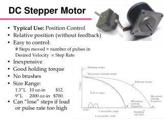
Stepper Motor and PIC. DC motor Command and control Stepper motor Function Driver Pic and stepper Motor. DC motor control: circuit 1. DC motor Control : circuit 2. Stepper Motor: Definition. B is always towards N Here: 8 steps, 45degres per step. Unipolar stepper Motor.

E N D
Stepper Motor and PIC DC motor Command and control Stepper motor Function Driver Pic and stepper Motor
Stepper Motor: Definition B is always towards N Here: 8 steps, 45degres per step
Unipolar stepper Motor Full step : 90 degres per step, Winding 1a 1100110011001100110011001 Winding 1b 0011001100110011001100110 Winding 2a 0110011001100110011001100 Winding 2b 1001100110011001100110011
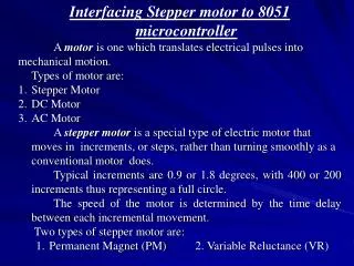
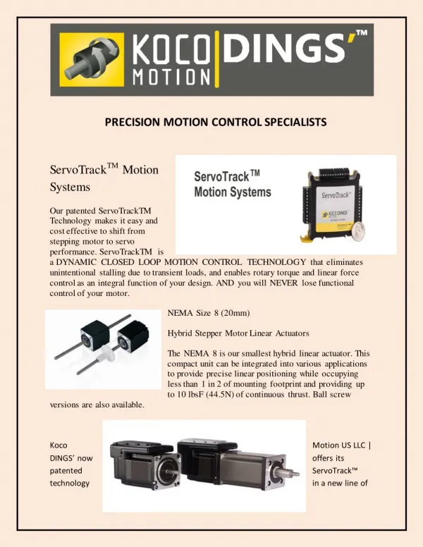
Variable reluctance SM • In use, the common wire typically goes to the positive supply and the windings are energized in sequence. • The cross section shown in Figure is of 30 degree per step variable reluctance motor. The rotor in this motor has 4 teeth and the stator has 6 poles, with each winding wrapped around two opposite poles. With winding number 1 energized, the rotor teeth marked X are attracted to this winding's poles. If the current through winding 1 is turned off and winding 2 is turned on, the rotor will rotate 30 degrees clockwise so that the poles marked Y line up with the poles marked 2. • Resolution Angle=360/(number of steps)
Other type variable reluctance Resolution increases with the Number of teeth and the number of poles
Variable reluctance SM • In use, the common wire typically goes to the positive supply and the windings are energized in sequence. • The cross section shown in Figure is of 30 degree per step variable reluctance motor. The rotor in this motor has 4 teeth and the stator has 6 poles, with each winding wrapped around two opposite poles. With winding number 1 energized, the rotor teeth marked X are attracted to this winding's poles. If the current through winding 1 is turned off and winding 2 is turned on, the rotor will rotate 30 degrees clockwise so that the poles marked Y line up with the poles marked 2.
Unipolar stepper Motor • the current flowing from the center tap of winding 1 to terminal a causes the top stator pole to be a north pole while the bottom stator pole is a south pole. This attracts the rotor into the position shown. If the power to winding 1 is removed and winding 2 is energised, the rotor will turn 30 degrees, or one step. We can also make a half step command: • Winding 1a 11000001 11000001 11000001 11 • Winding 1b 00011100 00011100 00011100 00 • Winding 2a 01110000 01110000 01110000 01 • Winding 2b 00000111 00000111 00000111 00
Microcontroller Output Table Sequenced for Half-Stepping
PIC and stepper motor • Write a program to make 200 steps upwards, full steps, and 150 steps forwards, half steps.