Download

1 / 13
130 likes | 354 Views
Team 2 Solar Kiosk Project. Sponsored by: Team Members: Jakub Mazur - Manager Eric Tarkleson – Presentation/Lab Josh Wong - Webmaster Ben Kershner – Document Preparation. Current Sensing. Applications Pros Cons The Hall Effect Shunt Resistors Making your Data useful Questions.

E N D
Team 2Solar Kiosk Project Sponsored by: Team Members: Jakub Mazur - Manager Eric Tarkleson – Presentation/Lab Josh Wong - Webmaster Ben Kershner – Document Preparation
Current Sensing • Applications • Pros Cons • The Hall Effect • Shunt Resistors • Making your Data useful • Questions
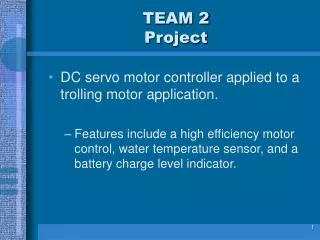
Applications • Measuring Power Consumption • Design for Safety • GFCIs, fuses, circuit breakers • Temperature optimization • High current = hotter components
Shunt Resistor Low failure probability Cheap Wastes power Limited sensing range Requires additional voltage measurements Hall Effect Sensor Isolated from current source Higher precision More expensive Can be integrated into an IC device
Who is this Guy? André-Marie Ampère (1775 –1836) By1800 scientists where wondering if electricity and magnetism where related. Ampere was one of the first to develop a technique for measuring electricity… essentially a compass with wire wrapped around it. Electrodynamics Electromagnetics, where studied at this time by: Faraday, Weber Thomson and Maxwell.
Shunt Resistor V = IR
The Hall Effect • When there is a Magnetic field in the presence of a conductor a voltage is induced due to electron and hole drift • Electron – negative charge carrier • Hole – positive charge carrier
B + + + EHp EHn Hall Effect VH t W L I +
The Hall Effect - Math • Vhall = -(I*B)/(d*n*e) • Rhall = -1/(n*e) current through wire • Bfield = Uo*Ip/(2*pi*r) • I= current • B = Mag Flux Dens • d = depth of plate • e = electric charge • j = current density • n = charge carrier dens • r = distance to center of wire • Uo = 4*pi*10^-7
So what? • We can use this to our advantage • We can detect • B field • Current • Voltage • Charge drift velocity • We can do this without having inline components (like a shunt resistor)
How do I handle this data? • Many types of signals • Reference voltage (LEM sensors) • Voltage drop (Shunt resistor) • Parallel bus (Some ADCs) • Serial interface (Some ADCs, other ICs) • Traditional Serial Interface • I2C Bus
How do I handle this data? • Sampling by digital ICs • Direct • Indirect • Intermediate ADC • Direct • Built-in ADC on the PIC • Inaccuracies • Parallel • High Pin Count
Serial Buses • Traditional UART/USART Serial • Typically one-to-one communication • Parity checking • Serial Protocols • I2C • Developed by Philips • 128 Devices on one bus • USB • Driver implementation