Download
1 / 21
250 likes | 1.24k Views
Grounding of Airfield Lighting . Joseph Vigilante, PE Penn State/FAA Hershey Conference 2009. Grounding of Airfield Lighting. “In the Fairytale of electrical design, Grounding is the Ugly Duckling.” Definition Objective Standards Recommended Values Soil Resistivity Calculation Design

E N D
Grounding of Airfield Lighting Joseph Vigilante, PE Penn State/FAA Hershey Conference 2009
Grounding of Airfield Lighting “In the Fairytale of electrical design, Grounding is the Ugly Duckling.” • Definition • Objective • Standards • Recommended Values • Soil Resistivity • Calculation • Design • Summary
Grounding of Airfield Lighting NEC 250.2 – Effective Ground-Fault Current Path “An intentionally constructed, low impedance electrically conductive path designed and intended to carry current under ground-fault conditions from the point of a ground fault on a wiring system to the electrical supply source and that facilitates the operation of the OCPD or GFD on high-impedance grounded systems.”
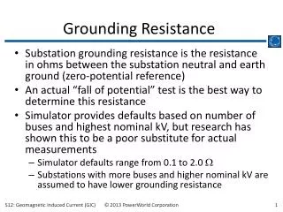
Grounding of Airfield Lighting The Objective: In ground system design, the objective is to achieve the lowest ground resistance value possible that makes sense economically and physically.
Grounding of Airfield Lighting Standards: • National Electrical Code (NEC) • FAA AC 150/5340-30D • FAA-STD-19e – Lightning and Surge protection, Grounding, Bonding and Shielding Requirements for Facilities And Electronic Equipment
Grounding of Airfield Lighting National Electrical Code (NEC) 250.56 A single electrode consisting of a rod… that does not have a resistance to ground of 25 ohms or less shall be augmented by one additional electrode…
Grounding of Airfield Lighting NEC 250.53 & 58 …. Two or more grounding electrodes that are bonded together shall be considered a single grounding electrode system.
Grounding of Airfield Lighting FAA AC 150/5340-30D 12.6. SAFETY (EQUIPMENT) GROUND … A safety ground must be installed at each light fixture…. The safety ground must be a #6 AWG bare jumper connected to the ground lug at the fixture base or stake to a 5/8 inch (16 mm) by 8 foot (2.4 m) minimum ground rod installed beside the fixture. The resistance to ground of the stake must be 25 ohms or less per measurement with a ground tester.
Grounding of Airfield Lighting FAA -STD- 19e Section 4.2.4 Earth Electrode System Requirements Sub-section 4.2.4.3 Design ….The design goal for the resistance to earth of the EES shall be as low as practicable and not over 10 ohms.
Grounding of Airfield Lighting Recommended Values: Using a 20% buffer, Design Range is 10-20 ohms
Grounding of Airfield Lighting Soil Resistivity Measurement ρ = (2) (п) (A) (R) ρ = Average Soil Resistance to Depth A in ohm-cm A = Distance between Electrodes in cm R= Measured Resistance Value in ohms Using a 3 m (10’) Ground Rod, Assume R measured value of 100 Ω ρ = 2 x 3.1416 x 3 m x 100 Ω = 1885 Ω·m
Grounding of Airfield Lighting Soil Resistivity Tabulated Boring Log • 0 – 2ft – Poorly Graded Gravel • 2 – 4 ft – Sandy Lean Clay w/Gravel • 4 – 13 ft – Silty Sand
Grounding of Airfield Lighting Soil Resistivity Tabulated • Data table • Average values • Non-specific to site
Grounding of Airfield Lighting Soil Resistivity Tabulated • 10 ft. ground rod • 0 – 2ft – Poorly Graded Gravel • 2 – 4 ft – Sandy Lean Clay w/Gravel • 4 – 13 ft – Silty Sand
Grounding of Airfield Lighting Resistance To Ground • IEEE Green Book Chapter 4 • 10 ft (3m) Ground Rod, 5/8” Diameter • Rg = ρ / (2 x п x L x ln (4L/a -1)) • Rg = ρ (Ω·cm) / 335 cm
Grounding of Airfield Lighting Range of Soil Resistivity • Rg = 10 Ω – 20 Ω • ρ = Rg (Low) x 335 cm - Rg (High) x 335 cm • ρ (Ω·cm) = 3350 Ω·cm - 6700 Ω·cm
Grounding of Airfield Lighting Ground Resistance Adjusted • ρ = 10,000 Ω·cm • Rg = 10kΩ·cm / 335 = 29.8 Ω • IEEE Chapter 4, Multiple Rods Factor • Using 2 Rods: Rg (adjusted) = (Rg/2) x 1.16 • Rg (adjusted) = 17.3 Ω
Grounding of Airfield Lighting Bonding Jumper • #6 AWG , Bare Copper • NEC Table 8 Conductor Properties • 0.491 Ω/kFT
Grounding of Airfield Lighting Grounding System • 2 Ground Rods At Each Location • 500 FT Spacing • #6 AWG , Bare Copper
Grounding of Airfield Lighting Summary • Obtain Boring Reports • Field Measure Soil Resistivity • Calculate Ground Resistance • Specify Ground Resistance Testing – During Installation and After • Obtain and Review Results • Improve Your Design Process
Grounding of Airfield Lighting Questions?