Download
1 / 27
270 likes | 414 Views
Dictionary-Less Defect Diagnosis as Surrogate Single Stuck-At Faults Chidambaram Alagappan Vishwani D. Agrawal. Department of Electrical and Computer Engineering Auburn University, AL 36849 USA. Presentation Outline. Purpose Introduction to Fault Diagnosis Diagnosis Algorithm

E N D
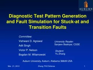
Dictionary-Less Defect Diagnosis as Surrogate Single Stuck-At Faults Chidambaram Alagappan Vishwani D. Agrawal Department of Electrical and Computer Engineering Auburn University, AL 36849 USA
Presentation Outline • Purpose • Introduction to Fault Diagnosis • Diagnosis Algorithm • Proposed Algorithm • Analysis of the Algorithm • Experimental Results • Conclusion
Purpose • Scalingdown of device features to an extent that it can be expressed in two digit number of nanometers has made VLSI chipmanufacturing often suffer a relatively low initial yield. • Fault Diagnosis proves helpful in ramping up the yield. • Most fault diagnosis procedures are fault model dependent. • In this work, we propose a diagnosis procedure using single stuck-at fault analysis, without assuming that the actual defect has to be a stuck-at fault.
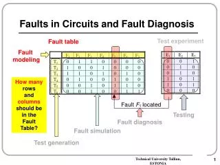
Fault Diagnosis Test Vectors Diagnosis Algorithm Circuit Netlist Defective Circuit Actual Response Observed Response Possible Faults Compare
Fault Diagnosis Strategies • Cause-effect analysis • Builds simulation response database for modeled faults. • Not suitable for large designs. • Too much information increases resources used. • Effect-cause analysis • Analyzes failing outputs to determine cause. • Backward trace for error propagation paths for possible faults. • Memory efficient and suitable for large designs.
Prime Suspect and Surrogate Faults • A prime suspect fault must produce all observed failures. It provides a perfect match with observed failures. • A surrogatefault has some, but not all, characteristics of the actual defect in the circuit. • A surrogate fault is not believed to be the actual defect. • A surrogate can only partially match symptoms of the actual defect. • Surrogates are representatives of the actual defect and may help identify the location or behavior of the defect. • L. C. Wang, T. W. Williams, and M. R. Mercer, “On Efficiently and Reliably Achieving Low • Defective Part Levels," in Proc. International Test Conf., Oct. 1995, pp. 616-625.
Output Selection C17 Benchmark Circuit C17 circuit with output selection
The Diagnosis Algorithm • The Diagnosis algorithm consists of 4 phases. • Assumption: No circular fault masking is present in the circuit. • The following nomenclature is used throughout the diagnosis procedure: • passing_set – Test patterns producing fault-free response • failing_set – Test patterns producing faulty response • sus_flts – Suspected fault list • set1_can_flts – Set of prime suspect fault candidates • set2_can_flts – Set of surrogate fault candidates
The Diagnosis Algorithm Phase I Phase II PhaseIII Phase IV
Fault Ranking Fault ranking is needed when both fault lists, set1_can_flts and set2_can_flts, are empty. Rank of a fault F= (#failing patterns detecting F) – (#Passing patterns detecting F) Highest ranked faults are placed in set1_can_flts and second highest ranked faults are placed in set2_can_flts. All lower ranked faults are discarded. The numerical ranks can be zero or even negative.
Fault Ranking (contd..) Faults detected by failing pattern Suspects No suspect found Faults detected by passing pattern
A Theorem If there is only a single stuck-at-fault present in the circuit under diagnosis (CUD), the diagnosis algorithm will always identify that fault, irrespective of the detection or diagnostic coverage of the test pattern set.
Experimental Results • Results for every circuit were obtained by calculating the average values from two separate runs of experiments, each containing 50 random failure cases (except for C17, which has only 22 faults). • Circuit modeling and algorithm – Python • Mentor Graphics Fastscan– ATPG and Fault simulator • Test pattern manipulation – VBA Macros
Diagnostic Coverage • Diagnostic coverage based on single stuck-at faults, excluding redundant faults is defined as • Fault Ratio for every set is defined as • Fault Ratio (FR) = (#Expected faults) / (#Reported faults) • Y. Zhang and V. D. Agrawal, “An Algorithm for Diagnostic Fault Simulation,” in Proc. 11th Latin-American Test Workshop (LATW), Mar. 2010, pp. 1–5.
Single Fault Diagnosis with 1-Detect Tests *PC with Intel Core-2 Duo 3.06GHz Processor and 4GB Memory
Single Fault Diagnosis with 2-Detect Tests * PC with Intel Core-2 Duo 3.06GHz Processor and 4GB Memory
Multiple Fault Diagnosis with 1-Detect Tests * PC with Intel Core-2 Duo 3.06GHz Processor and 4GB Memory
C499 (32-bit single error correcting circuit) • C499 has an XOR tree with 104 two input XOR gates. • XOR gates are not elementary logic gates. Set of faults depends on its construction. • Presence of circular fault masking. Probability of circular fault masking will reduce with increase in number of faults.
Multiple Fault Diagnosis with 2-Detect Tests * PC with Intel Core-2 Duo 3.06GHz Processor and 4GB Memory
Single Fault Diagnosis with Diagnostic Tests Multiple Fault Diagnosis with Diagnostic Tests * PC with Intel Core-2 Duo 3.06GHz Processor and 4GB Memory
Conclusion • Considering fault simulation tools will always be limited to a few fault models, the relationship between non-classical faults and their surrogate classical faults was explored. • The proposed algorithm proves to be memory efficient and utilizes reduced diagnostic effort. • Physical relation of the actual non-classical faults not diagnosed should be examined with respect to the functional relation of the reported faults. • For future work, other non-classical faults (bridging, stuck-open, coupling, delay, etc.) and their surrogates can be examined.
References M. Abramovici and M. A. Breuer, “Multiple Fault Diagnosis in Combinational Circuits Based on an Effect-Cause Analysis,” IEEE Transactions on Computers, vol. C-29, no. 6, pp. 451–460, June 1980. M. L. Bushnell and V. D. Agrawal, Essentials of Electronic Testing for Digital, Memory and Mixed-Signal VLSI Circuits. Boston: Springer, 2000. J. L. A. Hughes, “Multiple Fault Detection Using Single Fault Test Sets,” IEEE Trans.Computer-Aided Design of Integrated Circuits and Systems, vol. 7, no. 1, pp. 100–108, Jan.1988. Y. Karkouri, E. M. Aboulhamid, E. Cerny, and A. Verreault, “Use of Fault Dropping for Multiple Fault Analysis,” IEEE Transactions on Computers, vol. 43, no. 1, pp. 98–103, Jan.1994. N. Sridhar and M. S. Hsiao, “On Efficient Error Diagnosis of Digital Circuits,” Proc.InternationalTest Conference, 2001, pp. 678–687. C. E. Stroud, “A Designer’s Guide to Built-in Self-Test”. Boston: Springer, 2002. H. Takahashi, K. O. Boateng, K. K. Saluja, and Y. Takamatsu, “On Diagnosing Multiple Stuck-At Faults Using Multiple and Single Fault Simulation in Combinational Circuits,” IEEE Trans. Computer-Aided Design of Integrated Circuits and Systems, vol. 21, no. 3, pp. 362–368, Mar. 2002.
References (contd..) R. Ubar, S. Kostin, and J. Raik, “Multiple Stuck-at Fault Detection Theorem,” Proc. IEEE 15th International Symp. Design and Diagnostics of Electronic Circuits and Systems, Apr. 2012, pp. 236–241. L. C. Wang, T. W. Williams, and M. R. Mercer, “On Efficiently and Reliably Achieving Low Defective Part Levels,” Proc. International Test Conf., Oct. 1995, pp. 616–625. Y. Zhang and V. D. Agrawal, “A Diagnostic Test Generation System,” Proc. International Test Conf., Nov. 2010. Paper 12.3. V. D. Agrawal, D. H. Baik, Y. C. Kim, and K. K. Saluja, “Exclusive Test and Its Applications to Fault Diagnosis,” Proc. 16th International Conf. VLSI Design, Jan. 2003, pp. 143–148. L. Zhao and V. D. Agrawal, “Net Diagnosis Using Stuck-At and Transition Fault Models,” Proc. 30th IEEE VLSI Test Symp., Apr. 2012, pp. 221–226. Y. Zhang and V. D. Agrawal, “An Algorithm for Diagnostic Fault Simulation,” Proc. 11th Latin-American Test Workshop (LATW), Mar. 2010, pp. 1–5. C. Alagappan, “Dictionary-Less Defect Diagnosis as Real or Surrogate Single Stuck-At Faults,” Master’s thesis, Auburn University, Auburn, Alabama, May 2013.