Download
1 / 54
540 likes | 637 Views
This thesis discusses a fault diagnosis procedure using single stuck-at fault analysis in VLSI chip manufacturing to enhance yield by proposing fault diagnosis strategies.

E N D
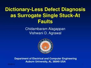
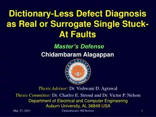
Dictionary-Less Defect Diagnosis as Real or Surrogate Single Stuck-At Faults Master’s DefenseChidambaram Alagappan • Thesis Advisor:Dr. Vishwani D. Agrawal • Thesis Committee:Dr. Charles E. Stroud and Dr. Victor P. Nelson Department of Electrical and Computer Engineering Auburn University, AL 36849 USA Chidambaram's MS Defense
Presentation Outline • Motivation • Introduction and Background • Problem Statement • Diagnosis Algorithm • Proposed Diagnosis Algorithm • Analysis of the Algorithm • Experimental Results • Conclusion Chidambaram's MS Defense
Motivation • Scalingdown of device features to an extent that it can be expressed in two digit number of nanometers has made VLSI chip manufacturing, often suffer a relatively low yield. • Fault Diagnosis proves helpful in ramping up the yield. • Most fault diagnosis procedures are fault model dependent. • In this work, we propose a diagnosis procedure using single stuck-at fault analysis, without assuming that the actual defect has to be a stuck-at fault. Chidambaram's MS Defense
Presentation Outline • Motivation • Introduction and Background • Problem Statement • Diagnosis Algorithm • Proposed Diagnosis Algorithm • Analysis of the Algorithm • Experimental Results • Conclusion Chidambaram's MS Defense
Fault Diagnosis Test Vectors Diagnosis Algorithm Circuit Netlist Defective Circuit Actual Response Observed Response Possible Faults Compare Chidambaram's MS Defense
Test Vector Set • Exhaustive Test Set – Apply every possible input combination. • Functional Test Set – Exercise every functional node with every possible data set. • Fault Model Derived Test Set – A test pattern for every modeled fault. • Automatic Test Pattern Generation (ATPG) can also identify redundant logic and prove whether one circuit implementation matches another. Chidambaram's MS Defense
Circuit Under Test • The Circuit Under Test (CUT) can be • Combinational Circuit: (time-independent logic) • Sequential Circuit: Chidambaram's MS Defense
Fault Simulation • Reverse of ATPG. Inputs – test patterns & fault list. • Fault Dropping Technique. • Fault Coverage (FC) – Quantitative measure of effectiveness of test vector set. • FC = (#Detected Faults)/(Total faults in fault list) • ATPG and Fault Simulator work interactively to achieve high FC. Chidambaram's MS Defense
Fault Models • Abstraction of a defect as an analyzable change in the chip. • Stuck-At Fault – Single and Multiple • Stuck-at 0 or Stuck-at 1. • Bridging Fault – WAND/WOR and Dominant • Low resistance short due to under etching. • Transistor Level Stuck Fault – Stuck open and Stuck short • SAF for Stuck open (memory effect). IDDQ testing for stuck short. • Delay Fault – Gate delay and Path delay • Gate delay – slow-to-fall and slow-to-rise transitions. • Path delay - Input to output timing unacceptable. Chidambaram's MS Defense
Fault Diagnosis Strategies • Cause-effect analysis • Builds simulation response database for modeled faults. • Not suitable for large designs. • Too much information increases resources used. • Effect-cause analysis • Analyzes failing outputs to determine cause • Backward trace for error propagation paths for possible faults. • Memory efficient and suitable for large designs. Chidambaram's MS Defense
Presentation Outline • Motivation • Introduction and Background • Problem Statement • Diagnosis Algorithm • Proposed Diagnosis Algorithm • Analysis of the Algorithm • Experimental Results • Conclusion Chidambaram's MS Defense
Problem Statement • Given the failing response of a defective circuit • Failing patterns • Erroneous outputs • Given the good circuit netlist • Verilog Description • Provide potential fault(s) or surrogates of the potential fault(s) which cause the circuit to fail. Chidambaram's MS Defense
Presentation Outline • Motivation • Introduction and Background • Problem Statement • Diagnosis Algorithm • Proposed Diagnosis Algorithm • Analysis of the Algorithm • Experimental Results • Conclusion Chidambaram's MS Defense
C432: Comparing with Fault Dictionary Chidambaram's MS Defense
Prime Suspect and Surrogate Faults • A prime suspect fault must produce all observed failures. It provides a perfect match with observed failures. • A Surrogate fault has some, but not all, characteristics of the actual defect in the circuit. • A surrogate fault is not believed to be the actual defect. • A surrogate can only partially match symptoms of the actual defect. • Surrogates are representatives of the actual defect and may help identify the location or behavior of the defect. • L. C. Wang, T. W. Williams, and M. R. Mercer, “On Efficiently and Reliably Achieving Low • Defective Part Levels," in Proc. International Test Conf., Oct. 1995, pp. 616-625. Chidambaram's MS Defense
Output Selection C17 Benchmark Circuit C17 circuit with output selection Chidambaram's MS Defense
Presentation Outline • Motivation • Introduction and Background • Problem Statement • Diagnosis Algorithm • Proposed Diagnosis Algorithm • Analysis of the Algorithm • Experimental Results • Conclusion Chidambaram's MS Defense
The Diagnosis Algorithm Phase I Phase II Phase III Phase IV Chidambaram's MS Defense
The Diagnosis Algorithm • The Diagnosis algorithm consists of 4 phases. • Assumption: No circular fault masking present in the circuit. • The following nomenclature is used throughout the diagnosis procedure: • passing_set – Test patterns producing fault-free response • failing_set – Test patterns producing faulty response • sus_flts – Suspected fault list • set1_can_flts – Set of prime suspect fault candidates • set2_can_flts – Set of surrogate fault candidates Chidambaram's MS Defense
Phase I Start with a failing_set containing ATE failing patterns. Step 1-1: If failing_setis empty, then restore with ATE failing patterns and go to Phase II. Else, remove a pattern from failing_set. Step 1-2: Perform fault simulation to identify detectable single stuck-at faults by the removed failing pattern. Step 1-3: Add all faults identified in previous step to the sus_flts list and go to Step1-1. Chidambaram's MS Defense
Phase I Chidambaram's MS Defense
Phase II Start with a passing_setcontaining ATE passing patterns. Step 2-1: If passing_setis empty, go to Phase III. Else, remove a pattern from passing_set. Step 2-2: Perform fault simulation for sus_flts to identify faults detectable by the removed pattern. Step 2-3: Remove faults identified in Step 2-2 from sus_fltslist, and go to Step 2-1. Chidambaram's MS Defense
Phase II Chidambaram's MS Defense
Phase III Skip to fault ranking if sus_flts is empty. Step 3-1: Copy sus_flts list to set1_can_flts list and set2_can_flts list. Step 3-2: If failing_setis empty, go to Step 3-5. Else, remove a pattern from failing_set. Step 3-3: Perform fault simulation on set1_can_flts to identify faults not detected by the removed pattern. Step 3-4: Update set1_can_flts list by deleting the faults identified in Step 3-3. Go to Step 3-2. Step 3-5: Remove faults from set2_can_flts list that are common to set1_can_flts list and Go to Phase IV. Chidambaram's MS Defense
Phase III Chidambaram's MS Defense
Phase IV Start with set1_can_flts list. Step 4-1: If there is no unselected fault in set1_can_flts list, repeat Phase 4 for set2_can_flts list and then STOP. Else, select a fault and uncollapse it to obtain its corresponding equivalent set of faults. Step 4-2: Add the equivalent set of faults to set1_can_flts list. Step 4-3: Add opposite polarity faults for the selected fault and its equivalent set of faults to set1_can_flts list. Chidambaram's MS Defense
Phase IV Chidambaram's MS Defense
Why add opposite polarity faults? Chidambaram's MS Defense
Fault Ranking Fault ranking is needed when both fault lists, set1_can_flts and set2_can_flts, are empty. Rank of a fault F= (#failing patterns detecting F) – (#Passing patterns detecting F) Highest ranked faults are placed in set1_can_flts and second highest ranked faults are placed in set2_can_flts. All lower ranked faults are discarded. The numerical ranks can be zero or even negative. Chidambaram's MS Defense
Fault Ranking (contd..) Faults detected by failing pattern Both overlapped Faults detected by passing pattern Chidambaram's MS Defense
A Theorem If there is only a single stuck-at-fault present in the circuit under diagnosis (CUD), the diagnosis algorithm will always diagnose the fault, irrespective of the detection or diagnostic coverage of the test pattern set. Chidambaram's MS Defense
Presentation Outline • Motivation • Introduction and Background • Problem Statement • Diagnosis Algorithm • Proposed Diagnosis Algorithm • Analysis of the Algorithm • Experimental Results • Conclusion Chidambaram's MS Defense
Analysis of the algorithm Case 1: Single Fault F1 Syndrome: 11100 Phase I – F1 and F2 in sus_flts Phase II – No faults Phase III – F1 in set1_can_flts and F2 in set2_can_flts Phase IV – Equivalent and opposite polarity of F1 and F2 are added. Perfect Diagnosis Achieved. Chidambaram's MS Defense
Analysis of the algorithm (Contd..) Case 2: Single Fault F2 Syndrome: 10100 Phase I – F1 and F2 in sus_flts Phase II – Removes F1 from sus_flts Phase III – F2 in set1_can_flts Phase IV – Equivalent and opposite polarity of F2 are added. Perfect Diagnosis Achieved. Chidambaram's MS Defense
Analysis of the algorithm (Contd..) Case 3: Multiple Faults F1 & F2 (No Masking) Syndrome: 11100 Phase I – F1 and F2 in sus_flts Phase II – No Faults Phase III – F1 in set1_can_flts and F2 in set2_can_flts Phase IV – Equivalent and opposite polarity of F1 and F2 are added. Perfect Diagnosis Achieved. Chidambaram's MS Defense
Analysis of the algorithm (Contd..) Case 4: Multiple Faults F1 Masking F2 Syndrome: 11100 Phase I – F1 and F2 in sus_flts Phase II – No Faults Phase III – F1 in set1_can_flts and F2 in set2_can_flts Phase IV – Equivalent and opposite polarity of F1 and F2 are added. Perfect Diagnosis Achieved. Chidambaram's MS Defense
Analysis of the algorithm (Contd..) Case 5: Multiple Faults F2 Masking F1 Syndrome: 10100 Phase I – F1 and F2 in sus_flts Phase II – Removes F1 from sus_flts Phase III – F2 in set1_can_flts Phase IV – Equivalent and opposite polarity of F2 are added. Partial Diagnosis Achieved. Needs further testing for perfect diagnosis. Chidambaram's MS Defense
Analysis of the algorithm (Contd..) Case 6: Multiple Faults F1 Interfering with F2 (0 to 1) Syndrome: 11110 (F1 changes t3 of F2) Phase I – F1 and F2 in sus_flts Phase II – No faults Phase III – No faults in set1_can_flts Phase IV – Equivalent and opposite polarity of F1 and F2 are added. Perfect Diagnosis Achieved. No prime suspects. Chidambaram's MS Defense
Analysis of the algorithm (Contd..) Case 7: Multiple Faults F2 Interfering with F1 (1 to 0) Syndrome: 11100 (F2 changes t0 of F1) Phase I – F1 and F2 in sus_flts Phase II – No faults Phase III – F1 in set1_can_flts and F2 in set2_can_flts Phase IV – Equivalent and opposite polarity of F1 and F2 are added. Perfect Diagnosis Achieved. Chidambaram's MS Defense
Presentation Outline • Motivation • Introduction and Background • Problem Statement • Diagnosis Algorithm • Proposed Diagnosis Algorithm • Analysis of the Algorithm • Experimental Results • Conclusion Chidambaram's MS Defense
Experimental Results • Results for every circuit were obtained by calculating the average values from two separate runs of experiments, each containing 50 random failure cases (except for C17, which has only 22 faults). • Circuit modeling and algorithm – Python • Mentor Graphics Fastscan– ATPG and Fault simulator • Test pattern manipulation – VBA Macros Chidambaram's MS Defense
Diagnostic Coverage • Diagnostic coverage based on single stuck-at faults, excluding redundant faults is defined as • Fault Ratio for every set is defined as • Fault Ratio (FR) = (#Expected faults) / (#Reported faults) • Y. Zhang and V. D. Agrawal, “An Algorithm for Diagnostic Fault Simulation,” in Proc. 11th • Latin-American Test Workshop (LATW), Mar. 2010, pp. 1–5. Chidambaram's MS Defense
Single Fault Diagnosis with 1-Detect Tests * PC with Intel Core-2 Duo 3.06GHz Processor and 4GB Memory Chidambaram's MS Defense
Single Fault Diagnosis with 2-Detect Tests * PC with Intel Core-2 Duo 3.06GHz Processor and 4GB Memory Chidambaram's MS Defense
Multiple Fault Diagnosis with 1-Detect Tests * PC with Intel Core-2 Duo 3.06GHz Processor and 4GB Memory Chidambaram's MS Defense
C499 (32-bit single error correcting circuit) • C499 has an XOR tree with 104 two input XOR gates. • XOR gates are not elementary logic gates. Set of faults depends on its construction. • Presence of circular fault masking. Probability of circular fault masking will reduce with increase in number of faults. Chidambaram's MS Defense
Multiple Fault Diagnosis with 2-Detect Tests * PC with Intel Core-2 Duo 3.06GHz Processor and 4GB Memory Chidambaram's MS Defense
Single Fault Diagnosis with Diagnostic Tests Multiple Fault Diagnosis with Diagnostic Tests * PC with Intel Core-2 Duo 3.06GHz Processor and 4GB Memory Chidambaram's MS Defense
Presentation Outline • Motivation • Introduction and Background • Problem Statement • Diagnosis Algorithm • Proposed Diagnosis Algorithm • Analysis of the Algorithm • Experimental Results • Conclusion Chidambaram's MS Defense
Conclusion • Considering fault simulation tools will always be limited to a few fault models, the relationship between non-classical faults and their surrogate classical faults was explored. • The proposed algorithm proves to be memory efficient and utilizes reduced diagnostic effort. • Physical relation of the actual non-classical faults not diagnosed should be examined with respect to the functional relation of the reported faults. • For future work, other non-classical faults (bridging, stuck-open, coupling, delay, etc.) and their surrogates can be examined. Chidambaram's MS Defense