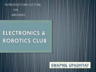
ELECTRONICS CLUB
ELECTRONICS CLUB. Electromania lecture and problem statement discussion. A quick review. Electronic Circuits: Analog and Digital. Analog. Digital. Digital Electronics. Deals with discrete values Voltage higher than a particular threshold corresponds to 1.

ELECTRONICS CLUB
E N D
Presentation Transcript
ELECTRONICS CLUB Electromania lecture and problem statement discussion
Electronic Circuits: Analog and Digital Analog Digital
Digital Electronics • Deals with discrete values • Voltage higher than a particular threshold corresponds to 1. • Voltage lower than that threshold corresponds to 0.
Number Systems - Decimal • We have decimal system with 10 numbers, viz 0,1,2,………,9 • Decimal number system 1 1 0 9 100= ones 101 = tens 102 = hundreds 103 = thousands 1*1000 + 1*100 + 1*10 + 9*1 = 1,109
Number Systems - Binary • Another method of number representation • Binary consists of two digits 0 and 1. 1 0 1 0 20= ones 21= twos 22 = fours 23 = eights 1*8 + 0*4 + 1*2 + 0*1 = 10(base-10) 1010(base-2) = 10(base-10)
What’s a clock? • At the basic level, just a special waveform. T
Flowchart Clock Pulse Counter Display
What hardware do we need? • IC(s) • Breadboards
What’s an IC? • An integrated circuit. • For our purposes, we will treat it as a black box. • We do not concern ourselves about the insides of an IC. • We look at it from the outside, from an input/output standpoint.
We will several three ICs today • 555 • 4029 • 7447 • Mux-Demux • Flipflops (4027) • Logic Gates (AND/OR/NOT)
The Clock – 555 (Astable Mode) 555 OUTPUT
555 in Monostable Mode • Generates Clock pulse when triggered 555 Monostable Mode Trigger OUTPUT
The Counter - 4029 4029 Counter • Output CLK
The Problem - Binary to Decimal? ?? 4029 Counter
The Solution - 7447 7447 4029 Counter
The Final Circuit 7447 555 Astable Mode 4029 Counter
AND GATE Truth Table(A.B)
OR GATE Truth Table(A+B)
NOT GATE Truth Table(~A)
XOR GATE Truth Table
Multiplexers • Multiple input, one output • A single line is connected electrically to the output • The selection of the input which is to be connected to the output is done via selection pins
What’s an Electrical Connection? • What we have are analog multiplexers • Not a digital connection • It is similar to the input and output being connected by a wire.
Demultiplexers • A mirror of the multiplexer • Multiple output, one input • One of the output is electrically connected to the input • The selection of the input which is to be connected to the output is done via selection pins
What Mux-Demux are available? • 4051 – 4bit Mux/Demux • 4052 – 8bit Mux/Demux
Using switches • Never leave a input pin unconnected. • Pull Up/Pull Down. ( ) ( )
Some Useful Advice • Tight, clean, non-overlapping connections, which must follow wire color conventions • Test each and every small part of the circuit, do not allow the circuit to grow too big before testing it. • Use gates for combining input, do not combine by direct shorting. • Do NOT leave any input pin unconnected, pull it up/down. • Do NOT divide one output into many wires. • Be very careful while making power connections: this may burn your IC. • Regularly meet club secretaries, and when needed, the coordinators.
Problem Statement • The aim of the competition is to design and build a “Crazy Taxi” using LEDs for display. • The object of the game is to avoid collisions with the incoming cars while driving on the wrong side of a busy road.
Compulsory feature #1 Roads of LEDs : • There must be at least 2 roads (rows) of LEDs with a minimum of 4 LEDs in each rows. • A car depicted by a glowing LED must move continuously in each of the rows.
Compulsory feature #2 Navigation keys for car • Left and Right navigation keys must be present to move the car in the horizontal direction.
Compulsory Feature #3 • Collision Detection: • In case of collision of the frog with the car, it must be detected by the circuit and a signal must be generated (either by glowing a LED or any other way possible).
Additional Features • Apart from the compulsory features, various additional features can be added to the circuit like • 1. 2 Cars on the same road instead of 1. • 2. Different levels of game with different speed of cars. • 3. Scoring Mechanism, etc. • 4. Pausing the game, reset score button
Join Us Website : http://students.iitk.ac.in/eclub/index.php FB Group : https://www.facebook.com/groups/eclub.iitk/ E-mail : eclub.iitk@gmail.com Youtube : http://www.youtube.com/user/electronicsclub
Contact Us Avi Singh A-129 / Hall 10 avisingh@iitk.ac.in8853544535 Kevin Jose 366/ Hall 2 kevinj@iitk.ac.in8127762331 PiyushAwasthi150/Hall 2 piyushst@iitk.ac.in9616384444