Download
1 / 19
190 likes | 220 Views
This study focuses on the implementation of a realistic module design and segmentation algorithm for the MUCH detector, which is used for measurements of vector meson decays. The purpose is to study in-medium modification of hadrons, chiral symmetry restoration, and deconfinement at high baryonic densities. The project plan includes the development of flexible software tools for realistic geometry simulations, implementation of passive materials and support structures, development of tracking algorithms for dimuon reconstruction, and optimization of absorbers and detector segmentation. The expected result is a realistic detector concept that meets experimental challenges in an optimal and cost-effective way.

E N D
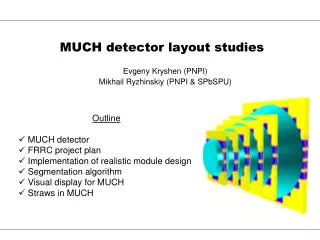
MUCH detector layout studies • Outline • MUCH detector • FRRC project plan • Implementation of realistic module design • Segmentation algorithm • Visual display for MUCH • Straws in MUCH Evgeny Kryshen (PNPI) Mikhail Ryzhinskiy (PNPI & SPbSPU)
MUCH detector • Purpose: measurements of • vector meson decays: • J/ψ →µ+µ- • φ→ µ+µ- • ω→ µ+µ- • Physics impact: in-medium modification of hadrons, chiral symmetry restoration, deconfinement at high baryonic densities. • The main design feature: sandwich stracture – active absorbers for the suppression of background hadrons and efficient tracking of signal muons FRRC seminar, 9 June 2009
Track statistics / central event FRRC seminar, 9 June 2009
FRRC Project plan • Research method based on Monte-Carlo simulation of detector response. • Framework: CBMROOT + UrQMD generator + Geant3. • Steps: • Development of flexible software tools aimed for realistic geometry simulations. • Implementation of passive materials and support structures. • Development of tracking algorithms tuned for dimuon reconstruction. • Development of visualization tools. • Optimization of absorbers: position, materials, thickness. • Optimization of detector segmentation. • Choice of detector type (GEM, micromegas, straws etc). • Main expected result: realistic detector concept which meets experimental challenges in the most optimal and cost-effective way. FRRC seminar, 9 June 2009
Old (simplified) design • Stations are simulated as simple shapes – 3 mm disks filled with argon gas • Distances between layers and absorbers are not realistic (too small) • No support structures, no module design • Parameter files are huge, full of irrelevant numbers, hardly readable, not flexible FRRC seminar, 9 June 2009
Module design in ALICE FRRC seminar, 9 June 2009
Schematic layout of GEM module Pads Readout electronics PCB Argon Spacer Support structure Fasteners GEM foils FRRC seminar, 9 June 2009
Implementation of module design Front side Back side Overlap • Layers: • Modules are arranged in rows on both sides of each layer • There is an overlap of active volumes to avoid dead zones in y direction FRRC seminar, 9 June 2009
Support structures and modules • Support structures: • Each support structure is composed of two parts to assure easy installation around the pipe • Estimated thickness ~ 1.5 cm • Material: carbon plastics (ρ = 0.1 ρC) • Implemented as composite shapes in cbmroot • Module: • Module size is mostly restricted by the GEM foil production technology • Active volume: 256 x 256 mm x 3 mm, argon • Spacers: 5 cm in y, 0.5 cm in x; material: noryl, implemented as composite shapes • Active volume implemented as TGeoBox for simple modules and as composite shapes for modules with a hole X spacers Active volume Y spacers FRRC seminar, 9 June 2009
Detailed geometry: general view Module design Simple design • Two layers at each station • Three layers at the last trigger station • Modules are automatically located on the surface of support structures • Cables, gas tubes, PCBs and front-end electronics are neglected at the moment FRRC seminar, 9 June 2009
Geometry input file: much_standard_straws.geo # General information MuchCave Zin position [cm] : 105 Acceptance tangent min : 0.1 Acceptance tangent max : 0.5 Number of absorbers : 6 Number of stations : 6 # Absorber specification Absorber Zin position [cm] : 0 40 80 120 170 225 Absorber thickness [cm] : 20 20 20 30 35 100 Absorber material : I I I I I I # Station specification Station Zceneter [cm] : 30 70 110 160 215 340 Number of layers : 2 2 2 3 3 3 Detector type : 1 1 1 2 2 2 Distance between layers [cm]: 10 10 10 7 7 7 Support thickness [cm] : 1.5 1.5 1.5 0.0 0.0 0.0 Use module design (0/1) : 1 1 1 0 0 0 # GEM module specification (type 1) Active volume lx [cm] : 25.6 Active volume ly [cm] : 25.6 Active volume lz [cm] : 0.3 Spacer lx [cm] : 0.5 Spacer ly [cm] : 5 Overlap along y axis [cm] : 2 # Straw module specification (type 2) Straw thickness [cm] : 0.4 FRRC seminar, 9 June 2009
Class hierarchy CbmMuchGeoScheme CbmMuchStation CbmMuchLayer CbmMuchLayerSide CbmMuchModule CbmMuchSector CbmMuchPad FRRC seminar, 9 June 2009
Automatic segmentation: algorithm y Hit density vs R x // Set minimum allowed resolution for each station Double_t sigmaXmin[] = {0.04, 0.04, 0.04, 0.04, 0.04, 0.04}; Double_t sigmaYmin[] = {0.04, 0.04, 0.04, 0.04, 0.04, 0.04}; seg->SetSigmaMin(sigmaXmin, sigmaYmin); // Set maximum allowed resolution for each station Double_t sigmaXmax[] = {0.32, 0.32, 0.32, 0.32, 0.32, 0.32}; Double_t sigmaYmax[] = {0.32, 0.32, 0.32, 0.32, 0.32, 0.32}; seg->SetSigmaMax(sigmaXmax, sigmaYmax); // Set maximum occupancy for each station Double_t occupancyMax[] = {0.05, 0.05, 0.05, 0.05, 0.05, 0.05}; seg->SetOccupancyMax(occupancyMax); FRRC seminar, 9 June 2009
Automatic segmentation: results Simple design Module design • Sector sizes at the first station are mostly determined by occupancy restrictions • Starting from the 3rd station sector sizes are determined by the required resolution • The smallest pad size in the default setup is ~2 mm (resolution ~ 600 μm). FRRC seminar, 9 June 2009
Visual Event Display: Layer view Layer view functionality: • Switch between stations and layers • Info on stations • Zoom • Show info on hits, points and sectors • Switch off sectors, modules, layer sides, hits and points • Select particles with required PDG code and mothers • Browse events • Clickable sectors producing zoomed module views FRRC seminar, 9 June 2009
Visual Event Display: Module View Zoomed module view Fired pads are marked with blue gradient colors reflecting the accumulated charge Found hits are marked with black markers FRRC seminar, 9 June 2009
Visual Event Display: Cluster View Cluster view can be opened by clicking on a cluster in a module frame. It is aimed to help in optimization of hit finding algorithms. FRRC seminar, 9 June 2009
Straw tubes in Much geometry 4 m; 4 mm robustness high detection efficiency 100% geom. acceptance 97%/m rate capability 4 MHz/cm2 spatial resolution 200 m radiation length 0.2 % X0 granularity > 10 cm2 occupancy > 10% FRRC seminar, 9 June 2009
Calendar plan FRRC seminar, 9 June 2009