Download
1 / 41
410 likes | 595 Views
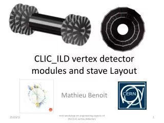
CLIC_ILD vertex detector modules and s tave Layout. Mathieu Benoit . Introduction. A more detailed description of the vertex detector layout is needed to drive the R&D ongoing on : Sensor and modules Cooling studies Signal and power distribution Mechanical support

E N D
CLIC_ILD vertex detector modules and staveLayout Mathieu Benoit mini workshop on engineering aspects of the CLIC vertex detectors
Introduction • A more detailed description of the vertex detector layoutisneeded to drive the R&D ongoing on : • Sensor and modules • Coolingstudies • Signal and power distribution • Mechanical support • Module dimensions are driven by Front-End and Sensor production capabilities • Chip has a maximum die size (2.2 x 2.2cm2) • Sensor has maximum length • Stavelayoutisdriven by : • Need for hermeticity • Module size • Occupancy in the layers (fixed radius) • Lorentz angle • Material budget mini workshop on engineering aspects of the CLIC vertex detectors
Module layout mini workshop on engineering aspects of the CLIC vertex detectors
Module Layout • Module dimensions are constrained by the size of the front-end • We suppose 512x512 pixel Timepix-like chips • 20x20 um pixel pitch • Modules per ladder must be an oddnumber (middle of a module at Z=IP) • Following CLIC_ILD CDR simulation layout, LadderLength = 26.0 cm • L=NbChip*(pitch) + (NbChip -1)*ChipGap + 2*GR • 5x(1.024)+4*0,005+2*0.001= 5.160 cm • 5x5.16cm = 25.8cm 6’’ Wafer, divided in squares of 1.029 x 1.029 cm2 mini workshop on engineering aspects of the CLIC vertex detectors
Module Layout (2) Physics and Detectors CDR ,Lucie LINSSEN, Akiya MIYAMOTO, Marcel STANITZKI, Harry WEERTS Wetry to stay as close as possible to the CLIC_ILD CDR layout, whith 2 different type of modules, for layer 1+2, and layer 3+4+5+6, locatedatfixed radius mini workshop on engineering aspects of the CLIC vertex detectors
Module Layout (3) mini workshop on engineering aspects of the CLIC vertex detectors
Module Layout (4) 45x45 um pixels at the corners • Inter-Chip regions • 20x45um pixel between set of 2 chips mini workshop on engineering aspects of the CLIC vertex detectors
Module Layout (5) • Interconnectionbetween chips wouldmake use of the TSV technology to bringread-out and power pads to the backside of the chip • DC/DC Converterstoragecapacitorcanbedistributed on the back of the chip on the Redistribution Layer (RDL) Bonding FE FE RDL TSV Pads sensor beam mini workshop on engineering aspects of the CLIC vertex detectors
Barrel layout mini workshop on engineering aspects of the CLIC vertex detectors
Barrels layout The CLIC ILD CDR Geometry for the CDR Monte Carlo Mass Production, A. Munnich, A. Sailer CDR layout has been selectedtakingintoaccountslightlywider module thanwhatisproposedhere. Weneed to modifyslightly the radius to keephermeticity, number of ladders (set of modules) Not mentionnedhereis the tilt angle of the modules with regard to the vertex radius, usually set by lorentz angle mini workshop on engineering aspects of the CLIC vertex detectors
Lorentz angle • It is a usual practice in vertex design to tilt modules with regard to the particle direction to account for Lorentz angle and minimize cluster size Reco hit E Holes Electrons Drift B= 5T mini workshop on engineering aspects of the CLIC vertex detectors
Lorentz angle Reco hit E B= 5T Holes Electrons Drift mini workshop on engineering aspects of the CLIC vertex detectors
Lorentz angle in CLIC_ILD • Lorentz angle depends on mobilitywhichdepends on Electric field and eventually on dopant concentration • In a 50um 10kOhmcm p-type wafer, 10V bias, E≈[1600,2700]V/cm • Varywithresistivity, bias voltage • In a planarsensor, E isproportional to V applied • V appliedisproportional to thickness2 (Full depletion voltage) • For thinsensor, at full depletion voltage, Electric fieldisverylow • To beinvestigated : How much over Full depletioncanweapply voltage mini workshop on engineering aspects of the CLIC vertex detectors
Lorentz angle in CLIC_ILD 80V (?) 10V mini workshop on engineering aspects of the CLIC vertex detectors
Lorentz angle in CLIC_ILD 10V 80V (?) mini workshop on engineering aspects of the CLIC vertex detectors
Lorentz angle in CLIC_ILD (summary) • Following the sensorspecification, lorentz angle willbe large in CLIC_ILD • It is not possible to specifyatthis point veryprecisely the characteristics of the sensor to beused • Unknownresistivity, thickness • Possible operation voltage • Best strategyis to deal withthisat the hit reconstruction level, by takingintoaccountmeasured angle (cosmics ? Runs w/o B Field?) mini workshop on engineering aspects of the CLIC vertex detectors
Barrel layout(layer 1+2) • CLIC_ILD MC Model Layer 1+2 are octodecagons (18) • Radius = 31.0, 32.87 mm • Length = 260 mm (25 chips + 2 mm tolerance) • Width (ladder) = 11.5 mm (all considered active) • Real Module and Layer (assuming 5x1 modules) • Radius = ?? • Length 258 mm (5x 5x1 chip modules) • Width (ladder) = 10.44 mm (10,24 mm active) mini workshop on engineering aspects of the CLIC vertex detectors
Barrel layout (layer 1+2) • To ensurehermeticity, layer 1+2 need to beplacedcloser to IP than MC model • Option 1: • Radius(layer 1) = 29 mm (31mm before) • Radius(layer 2) =30.87mm (32.87mm before) • To avoid volume overlap, slightly tilt the ladders (here1.5°) • Option 2: • Tilt sensors by lorentz angle (ex: 15 deg) • Add 1-2 ladders (here , 2-> Icosagon !) • Move back to larger radius (here31.221 mm) mini workshop on engineering aspects of the CLIC vertex detectors
Barrel layout (layer1+2, option 1) Single hits Double layer, holding on the samemechanical structure not shownhere An option to option 1: Shifting layer 2 vs layer 1 (here 1mm), ladder per ladder to avoidoverlapping gaps mini workshop on engineering aspects of the CLIC vertex detectors
Barrel layout (layer1+2, option 2) Single hits In this option wemaintain the larger radius, but increaseoverlap, further optimisation isneeded mini workshop on engineering aspects of the CLIC vertex detectors
Barrel layout(layer 3+4) • CLIC_ILD MC Model Layer 3+4 are tridecagons (13) • Radius = 44.0, 45.87 mm • Length = 260 mm (25 chips + 2 mm tolerance) • Width (ladder) = 22.5 mm (all considered active) • Real Module and Layer (assuming 5x2 modules) • Radius = ?? • Length 258 mm (5x 5x2 chip modules) • Width (ladder) = 20.73 mm (20.53 mm active) mini workshop on engineering aspects of the CLIC vertex detectors
Barrel layout (layer 3+4) • To ensurehermeticity, layer 3+4 need to beplacedcloser to IP than MC model • Option 1: • Radius(layer 1) = 41.65 mm (44 mm before) • Radius(layer 2) = 43.516 mm (45.87 mm before) • To avoid volume overlap, slightly tilt the ladders(here1.5°) • Option 2: • Tilt sensors by lorentz angle (ex: 15 deg) • Add 1-2 ladders (here , 2-> pentadecagon !) • Move back to larger radius (here45.647 mm) mini workshop on engineering aspects of the CLIC vertex detectors
Barrel layout (layer3+4, option 1) Single hits mini workshop on engineering aspects of the CLIC vertex detectors
Barrel layout (layer3+4, option 2) mini workshop on engineering aspects of the CLIC vertex detectors
Barrel layout(layer 5+6) • CLIC_ILD MC Model Layer 3+4 are heptadecagons (17) • Radius = 58.0, 59.87 mm • Length = 260 mm (25 chips + 2 mm tolerance) • Width (ladder) = 22.5 mm (all considered active) • Real Module and Layer (assuming 5x2 modules) • Radius = ?? • Length 258 mm (5x 5x2 chip modules) • Width (ladder) = 20.73 mm (20.53 mm active) mini workshop on engineering aspects of the CLIC vertex detectors
Barrel layout (layer 5+6) • To ensurehermeticity, layer 5+6 need to beplacedcloser to IP than MC model • Option 1: • Radius(layer 1) = 54.91 mm (58 mm before) • Radius(layer 2) = 56.782mm (59.87 mm before) • To avoid volume overlap, slightly tilt the ladders(here1.5°) • Option 2: • Tilt sensors by lorentz angle (ex: 15 deg) • Add 1-2 ladders (here , 2-> enneadecagon !) • Move back to larger radius (here58.418 mm) mini workshop on engineering aspects of the CLIC vertex detectors
Barrel layout (layer 5+6, option 1) mini workshop on engineering aspects of the CLIC vertex detectors
Barrel layout (layer 5+6, option 2) mini workshop on engineering aspects of the CLIC vertex detectors
Full Barrel (option 1) mini workshop on engineering aspects of the CLIC vertex detectors
mini workshop on engineering aspects of the CLIC vertex detectors
Full Barrel (option 2) mini workshop on engineering aspects of the CLIC vertex detectors
Full Barrel (option 3) • SiDlike design • Symmetriclayout • Unregular hit distance to IP mini workshop on engineering aspects of the CLIC vertex detectors
Disklayout mini workshop on engineering aspects of the CLIC vertex detectors
Disklayout The CLIC ILD CDR Geometry for the CDR Monte Carlo Mass Production, A. Munnich, A. Sailer Wheels in CLIC_ILD CDR layoutconsist of 3 identical double-layers mini workshop on engineering aspects of the CLIC vertex detectors
Wheel layout (2) • The wheel active area spansfromR=33 to R=102mm H=69 mm in CLIC_ILD CDR layout • To use module like building block, the best option is 6x2 modules • H=61.89 mm < CDR layout • Dimension couldbeadjusted a bit making use of elongated pixels mini workshop on engineering aspects of the CLIC vertex detectors
Wheel layout, the quadrature of the circle (option 1) • Module basedlayout • 15 modules per layer, 30 for a double layer • Each module tilted by 24° with regard to previous layer • Each layer tilted by 12° with regard to other part of double layers • Each module tilted by 2° with regard to radius to allowoverlap • Possibility to distribute modules along Z to reproduce the helicoidal structure favored for cooling mini workshop on engineering aspects of the CLIC vertex detectors
Wheel layout, the quadrature of the circle (option 1) mini workshop on engineering aspects of the CLIC vertex detectors
Wheel layout, the quadrature of the circle (option 1) mini workshop on engineering aspects of the CLIC vertex detectors
mini workshop on engineering aspects of the CLIC vertex detectors
Wheel Layout (option 2) Source : http://www.micronsemiconductor.co.uk/pdf/cat.pdf mini workshop on engineering aspects of the CLIC vertex detectors
Conclusion • A set of specifications for the modules driven by the acheivable Front-end and sensor die size has been established • Inactive regionmust betakenintoaccount in the layout of the ladders, barrel and disks • Hermeticity of the double layer must beminimized • Lorentz angle in the sensorshouldbetakenintoaccount in the layout of the barrel • Possibility of cableless power distribution and readoutshouldbeexplored • Stitchingbetween Front-End and between modules (TSV,RDL) • Integration of components (capacitor, resistance) on Front-End backside • Disklayoutrepresent a challenge in terms of material budget, hermeticity and mechanical support • Radial distribution of modules (option 1) is far from the ideal in terms of hermeticity and material budget • Disklike modules couldbe a solution (one module per wafer, assemblychallenging) mini workshop on engineering aspects of the CLIC vertex detectors