Download
1 / 10
100 likes | 189 Views
Terminal gas stripper design of K-State 7MV tandem. Notes, photos, technical drawings and discussion with Kevin Carnes ( For APAPES WP2). Here's a picture of the turbo. It's not shown on the earlier drawings I sent you.

E N D
Terminal gas stripper design of K-State 7MV tandem Notes, photos, technical drawings and discussion with Kevin Carnes (For APAPES WP2)
Here's a picture of the turbo. It's not shown on the earlier drawings I sent you. On our EN, there was a blanked off port at the bottom of the stripper box (which came with the EN originally). The guys enlarged that port and installed the turbo on it. It's directly underneath the inlet shown on the lid. In the lid picture that I sent (lid top view), the beam (and therefore the LE end) is coming from the upper left corner of the picture. The turbo is directly below that inlet in the center of the picture. On the two schematic drawings of the stripper canal I sent, the beam (and therefore the LE end) is coming from the right side of the picture. Yes, all of that fits inside the stripper box, the lid of which is shown in the lid picture, and the bottom of which is shown in the turbo picture attached to this e-mail. Have the tandem guys in Athens look at the pictures. They should recognize the stripper box and portions of the column visible in the pictures. Let me know if you have other questions. The turbo is an Alcatel 5150CThe pump is wired directly into the Georator that runs off one of the chain drives. So, if that chain is on, the turbo is running. No controller is needed.
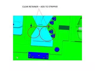
Lid top view Turbo recirculated exhaust
Discussion via e-mail with Kevin Carnes (kdc@phys.ksu.edu) Theo - Looking at the picture called kanal2 I see the basic idea: The stripper is a roughly 28" pipe of close to 2" OD in which the gas circulates and is differentially pumped through the openings of the pipe on either side having ID of about 0.6". Is that about right? Kevin -- We measured off the original drawings this morning. The pipe is 23.275" long, the OD is 1.25", and the ID of the central part of the canal is .6". At either end of the canal is an insert with a .25" hole which is tapped to a depth of .75" with a 5/16" 18 tap. This spiral tap helps slow down the escaping gas. The stripper box itself (which contains the canal) also has apertures, a 5/16" tap of a .25 hole at the entrance of the box and a 3/8" tap of a 5/16" hole at the box exit. Theo - What kind of pressures did you run in the stripper canal (50-100mTorr?) and how big was the turbo in the picture. I seem to recall the vacuum with loaded stripper in the terminal tubes was till about 10-6 Torr? Kevin - We have never had any way to measure the actual pressure inside the canal. A pressure at the high energy end in the low 10-6 Torr range corresponds to a pressure inside the box (not the canal) of 10-4 Torr. You are probably correct in that the pressure inside the canal is a few 10's of mTorr, but we don't really know that. The turbo is an Alcatel 5150C.
Theo - I guess all tandems come with an enclosed terminal in which a gas stripper canal can be placed as you did. It seems nowadays you can even order your tandem with such a stripper as an option? Didn't the K-State tandem have such a stripper canal when originally bought? Kevin - The K-State tandem did indeed have a gas stripper originally, along with a 14-foil stripper. Early on, the 14-foil unit from HVEC was replaced with a homemade 60 foil unit. Later, in the mid 1990's, we added the recirculating turbo and an additional 256 foil NEC unit. At that time, we had to shorten the stripping canal by several inches to its current length. The NEC stripper was upstream (it has now been removed) and the 60-foil stripper is downstream from the canal. Theo – What is the main advantage of such a gas stripper? From my experience it is particularly valuable at the lower collision energies where interaction of ions with C-foils is very strong thus limiting their life time to just a few tens of minutes. A gas stripper solves this problem while still providing adequate stripping. Are there any other reasons for installing such a stripper? Particularly for nuclear physics guys who i will have to convince? Kevin -- As far as I know, you've described the main reasons for having a gas stripper. If you want to know more, you'll have to look it up yourself, perhaps by contacting NEC.
Theo - Where in the drawing is the C-foil stripper? Upstream or downstream? Kevin - Downstream, see above. Theo - How does the gas stripper affect the transmission of the beam? I would guess quite significantly unless the beam optics is very good. Thus, the nuclear physicists running intense proton beams that would have to go through this canal would probably loose quite some intensity? Right? or is the beam there so well focused that this is not a real problem? Kevin -- Since we have always had the stripper, I can't give you a with/without comparison. I think that the beam is well focused there (you have to tune it that way), but I don't know the actual effect. Bob finds it hard to believe that there isn't already a gas stripper canal in the Demokritos tandem. Without it, how do you make sure you're going through the foil? Theo - How much do you think the whole K-State modification cost? Who designed the gas stripper? Was that Tom Gray? Kevin -- No idea on cost, since the gas stripper was original. Tom did the design on the later modification (the recirculating turbo and the 256 foil unit).
Theo - I found out that indeed there might well be a stripper canal inside which it seems they have used about 30 years ago and the newer people have never seen. So they will check to see next time they open up. Question: If they add a turbo for differential pumping of the terminal gas stripper as you have at K-State how do you extract the gases from the backing pump? Is the backing pump inside or outside the tank? You get my drift. In the photo you send I could not see how the turbo gases get pumped out. Kevin - Glad you found a gas stripper already there. The point of the turbo is to allow you to get a higher stripping pressure in the canal without using a lot of gas or having that gas degrade the pressure in the accelerating tubes. The turbo opening is on the bottom of the stripper box, and its exhaust feeds right back into the canal. It effectively compresses the gas that escapes the canal into the box and reuses it in the canal. If you look on the drawing that I sent, you'll see a smaller tube with a circular curl feeding into the top of the canal. That is the gas feed from the leak valve. To the right of that is a larger tube with sharp bends. That is where the turbo exhaust comes back in. The bolt circle on the top plate has a pipe that goes from there directly to the turbo.