1.5
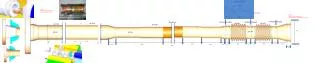
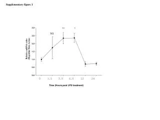
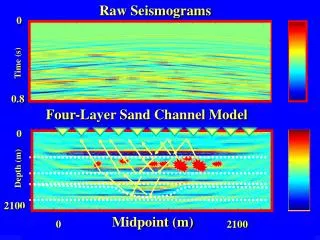
Raw Seismograms. 0. 6.0 -6.0. Time (s). 0.8. Four-Layer Sand Channel Model. 1.5. 0. Depth (m). -1.5. 2100. 0 2100. Midpoint (m). Interferometric Seismic Imaging. J. Yu, J. Sheng, and G. Schuster.

1.5
E N D
Presentation Transcript
Raw Seismograms 0 6.0 -6.0 Time (s) 0.8 Four-Layer Sand Channel Model 1.5 0 Depth (m) -1.5 2100 0 2100 Midpoint (m)
Interferometric Seismic Imaging J. Yu, J. Sheng, and G. Schuster
Arbitrary Unknown Src V(z) V(x,y,z) W(t) Location Claerbout, Katz, 70’s xx xx xy Migrate Utah+LLNL 1997 Claerbout, Rickett 1999 xy Migrate SELECTIVE HISTORY PASSIVE IMAGING Validity NO YES YES YES Earthquake 1900’s NO YES/NO YES NO YES NO YES YES YES YES/NO YES NO? YES YES YES YES
Outline • Interferometric Principle: Time Diff. between Arrivals Structure Diff. • Interferometric Imaging Applications: Passive data for IVSP while Drilling Imaging of Free Surface CDP Multiples Imaging of Hydo-Frac Location Transmission PS Migration
Interference Pattern t LASER Optical Lens Optical Lens Optical Lens
t LASER Lens Deformation Time Differences Interference Pattern s s Optical Lens
Outline • Interferometric Principle: Time Diff. between Arrivals Structure Diff. • Interferometric Imaging Applications: Passive data for IVSP while Drilling
Seismic Ghost Reflection Ghost Direct Find R(x,z) but not know source location ?
Master } t Kirchhoff Migrate psuedo-shot gathers m(x) = (g, t + t ) Direct Direct gx gx Mx g x x M Seismic Interferogram: Correlate Traces Seismic Ghost Reflection Ghost Direct 1 2 M
Geological Model X (m) 0 4 0 V1 V2 Depth (m) V3 V4 V5 V6 3
Shot Gather and Crosscorrelogram Traces Traces 1 200 1 200 0 0 Time (s) Time (s) 4 4 CSG 10 and Master trace at 80
Crosscorrelogram Migration Results X (km) X (km) 1.6 2.1 1.6 2.1 0 Time (s) 2.2 With primary Without primary
Geophone Pilot signal? Wavelet ? Bit Position? Source Problems in RVSPWD
Ghost Direct Wave Primary What is Joint Migration Receiver Well Drill bit
Acquisition Survey East (kft) 0 4.5 0 Drill bit North (kft) Well Rig 3C Receivers -5 0 Depth (kft) 10
Autocorrelograms of CSG 96 1 10 1 10 1 10 0 Time (s) 4 12 s 16 s 8 s
Line AC4 Acquisition Survey Map Well Rig 0 North (ft) Drill bit 3C Receivers -5000 0 1500 3000 4500 East (ft)
Joint Migration ( insert) and CDP Section SP 1255 1215 1235 1.0 Drilling hole Time (s) 2.0 3.0
Outline • Interferometric Principle: Time Diff. between Arrivals Structure Diff. • Interferometric Imaging Applications: Passive data for IVSP while Drilling Imaging of Free Surface CDP Multiples
Free-Surface Multiple Ghost Primary 1 2
} t Ghost Primary Primary = R Kirchhoff Migrate psuedo-shot gathers m(x) = (g, t + t ) 3 Primary Caution: gx gx Mx g x x x M Seismic Interferogram: Correlate Traces Ghost Primary 1 2
320 shots 176 traces per shot 0 5000 10000 15000 Distance (m) SEG/EAGE Salt Model 0 600 1200 1800 Depth (m) 2400 3000 3600
Distance (m) 0 5000 10000 15000 Kirchhoff Image 0 600 1200 1800 Depth (m) 2400 3000 3600
Distance (m) 0 5000 10000 15000 XcorM 0 600 1200 1800 Depth (m) 2400 3000 3600
XcorM Distance (m) 0 5000 10000 15000 KM 0 600 1200 1800 Depth (m) 2400 3000 3600
Distance (m) 0 5000 10000 15000 Kirchhoff Image 0 600 1200 1800 Depth (m) 2400 3000 3600
Outline • Interferometric Principle: Time Diff. between Arrivals Structure Diff. • Interferometric Imaging Applications: Passive data for IVSP while Drilling Imaging of Free Surface CDP Multiples Imaging of Hydo-Frac Location
P P 1 2 P P x Hydro-Fracturing=Unknown Source ? ?
P*P P*P } 1 2 x t Difference between Paths Kirchhoff Migrate psuedo-shot gathers m(x) = (g, t - t ) gx gx Mx g M Hydro-Fracturing=Unknown Source Master S P P P
70 Ringy 30 Hz Seismograms 0 1.0 Time (s) 0.8 Kirchhoff MigrationImage 0 -1.0 1.0 2100 m Correlogram MigrationImage -1.0 0 1.0 -1.5 2100 m 0 2100 Midpoint (m)
70 Raw Seismograms 0 1.0 Time (s) 0.8 Migration Image: 1-s Stack 0 2100 m Migration Image: 40-s Stack Migration Image: 40-s Stack 0 2100 m 0 2100 Migration Image: 1-s Stack -1.0 6.0 -6.0 1.5 -1.5 Midpoint (m)
Outline • Interferometric Principle: Time Diff. between Arrivals Structure Diff. • Interferometric Imaging Applications: Passive data for IVSP while Drilling Imaging of Free Surface CDP Multiples Imaging of Hydo-Frac Location Transmission PS Migration
P S S P Find R(x,z) Seismic P and PS Transmission ?
P*S S*S } 1 2 x t Difference between Paths Kirchhoff Migrate psuedo-shot gathers m(x) = (g, t - t ) gx Mx g M P and PS Transmission Interferograms Seismic P and PS Transmission Master P S S P
0 km 200 km 0 s 1.6 s
m(x) = (g, t + t ) M gx Mx 1. New Passive Seismic Imaging Capability: Valid for V(x,y,z) Arbitrary Sources Src & R Images Poststack & Prestack 2. Possible Applications: Horizontal Drill Bit Imaging, CDP Mult. Reservoir Monitoring, Mars/Sun Seismology 3. Limitations: Virtual Multiples Coherent Noise Reflectivity Imaging > Source Imaging g 2 N Traces N Correlograms Summary
Acknowledgements Thanks for support of UTAM sponsors. Thank J. Rickett and J. Claerbout for fruitful discussions.
m(x)= d(x, t + t - t ) sx gx red. Reduced-Time Migration Shift Traces by R1 Traveltime Mitigate Src-Rec Statics R1 R2
We only “see” Phase Difference Interference Pattern Phase Difference Phase of Rays with Common Path Cancels
Outline • Interferometric Principle: Phase Differences • Passive Seismic Data: Ghost Reflection Imaging • Synthetic Data Results • CDP Multiple Data: Ghost Reflection Imaging • Synthetic Data Results • Source Imaging & Transmission PS Imaging • Summary
Raw Seismograms 0 6.0 -6.0 Time (s) 0.8 Four-Layer Sand Channel Model 1.5 0 Depth (m) -1.5 2100 0 2100 Midpoint (m)
Outline • Interferometric Principle: Phase Differences • Passive Seismic Data: Ghost Reflection Imaging • Synthetic Data Results
Outline • Interferometric Principle: Phase Differences • Passive Seismic Data: Ghost Reflection Imaging • Synthetic Data Results • CDP Multiple Data: Ghost Reflection Imaging
Outline • Interferometric Principle: Phase Differences • Passive Seismic Data: Ghost Reflection Imaging • Synthetic Data Results • CDP Multiple Data: Ghost Reflection Imaging • Synthetic Data Results
Outline • Interferometric Principle: Phase Differences • Passive Seismic Data: Ghost Reflection Imaging • Synthetic Data Results • CDP Multiple Data: Ghost Reflection Imaging • Synthetic Data Results • Source Imaging & Transmission PS Imaging
Outline IVSPWD ? • Interferometric Principle: Phase Differences • F.S. CDP Multiple Migration F.S. CDP Multiples ? ? ?
Outline IVSPWD ? Hydro-Frac ? • Interferometric Principle: Phase Differences • Locating Hydro-Fractures in EOR F.S. CDP Multiples ? ? ? ? ?
Outline IVSPWD ? Hydro-Frac S P ? ? • Interferometric Principle: Phase Differences • PS Transmission Migration F.S. CDP Multiples ? ? ? ? PS Transmission Migration ? ?
Outline IVSPWD ? ? • Interferometric Principle: Phase Differences • Passive Seismic Data: Ghost Reflection Imaging ?
Outline IVSPWD ? Hydro-Frac ? • Interferometric Principle: Phase Differences • Locating Hydro-Fractures in EOR F.S. CDP Multiples ? ? ? ? ?