Download
1 / 43
440 likes | 753 Views
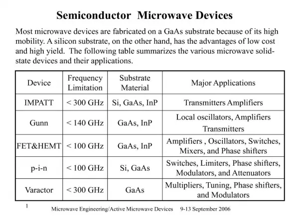
ECE 662 Microwave Devices. Microwave Materials, Diodes and Transistors February 3, 2005. Two-Terminal Negative Resistance Devices. Varactor – small pn diodes that are operated as nonlinear capacitors In the reverse bias region. Application of Negative Resistance Devices. Varactor.

E N D
ECE 662Microwave Devices Microwave Materials, Diodes and Transistors February 3, 2005
Two-Terminal Negative Resistance Devices Varactor – small pn diodes that are operated as nonlinear capacitors In the reverse bias region
Varactor • Varactor = Variable reactor • Use of voltage-variable properties (such as capacitance) of reversed-biased p-n junctions • Reverse biased depletion capacitance is given by Cj~ (Vb + VR)-n or Cj~ (VR)-n for VR >> Vb, where n = ⅓ for a linearly graded junction and n = ½ for an abrupt junction. • Can further increase the voltage sensitivity by using a hyperabrupt junction having an exponent n greater than ½.
Varactor • Present applications mostly for harmonic generation at millimeter and sub millimeter wave frequencies and tuning elements in various microwave applications. • A common varactor is the reversed biased Schottky diode. • Advantages: low loss and low noise. • Produces only odd harmonics when a sinusoidal signal is applied, so a frequency tripler can be realized without any second harmonic.
Varactor Frequency Multipliers • Provide LO power to sensitive millimeter and sub-millimeter wavelengths receivers. • Schottky doublers can deliver 55 mW at 174 GHz • Heterostructure Barrier Varactor Diodes acting as triplers deliver about 9mW at 248 GHz.
Varactor Devices • Lower frequencies: reversed biased semiconductor abrupt p+-n juction diodes made from GaAs or Si. • Higher frequencies: Schottky diodes (metal-semiconductor junction diodes • High frequencies and power handling: heterostructure barrier varactor – several barriers stacked epitaxially
Tunnel Diode • To achieve microwave capability • Device dimensions must be reduced • Parasitic capacitance and resistance must be minimized. • Tunnel diode • Associated with a quantum tunneling phenomenon • Tunneling time is very short permitting its use well into the millimeter region • Used for low power microwave application • Local oscillator, detectors, mixers, frequency locking circuit • Low cost, light weight, high speed, low-power operation, low noise
Tunnel Diode • In classical case, particle is reflected if E< potential barrier height of V0 • In quantum case particle has a finite probability to transmit or “tunnel” the potential barrier • Single p-n junction which has both p & n sides heavily dopeddepletion regions very narrow and tunneling distance is small ~ 50 to 100Å • (1 Å =10-8 cm=10-4 m) • High dopings cause Fermi levels within allowable bands
Tunnel Diode- abrupt junctions of heavily doped p & n semiconductor material p~n~1019
Tunnel Diode • 1) For zero bias - electrons tunneled through narrow barrier at equal rates in each direction. Net current zero. • 2) Small forward bias - electrons at bottom of conductor band on n side are are raised to energy levels corresponding to unoccupied energy levels on the p side. Therefore, tunneling current in forward direction with increases with bias.
Tunnel Diode • 3) For still larger bias, more and more electrons are raised to levels lying opposite the forbidden band on p side to which to which no tunneling is possible therefore the current reduces with increasing bias. • 4) As bias increases further, the current remains small until minority carrier injection similar to conventional diodes predominates.
Tunnel Diode • 5) with reverse as an increasing number of electrons on the p side find themselves opposited allowed and empty levels in the conduction band on the n side therefore tunneling increases rapidly with increasing bias.
Application of Negative Resistance Devices Note negative resistance
Tunnel Diode Note that small changes in VB result in large changes in i hence VRL Negative Resistance Devices I & V, 180 out of phase I2R power absorbed, but if R –R then power generated
Summary of Tunnel Diode • Quantum Tunneling Phenomena • Tunneling time short - mm waves • Low-power applications • n-p sides so heavily doped that the fermi levels lie within the conduction and valence bands • Good for extreme speed • Rate of tunneling can change as fast as energy levels can be shifted • Devices such as transistors give more power, but traditionally have suffered in speed due to rate of diffusion of charge changing.
Solid-State Device Power Output vs Frequencyref: Sze and modifiedby Tian
Transistors • Bipolar (Homojunction) • Inexpensive, durable, integrative, relatively high gain • Bipolar (Heterojunction) • High speed switching • Field Effect Transistors • Junction • MESFET, MOSFET, High Electron Mobility (HEMT) • Av as well as Qc, better efficiency, lower noise figure, higher speed, high input impedance
pnp transistor with all leads grounded ref. Sze
pnp transistor in the active mode of operation ref. Sze
Various current components in a p-n-p transistor under the active mode of operation. ref. Sze
Field-Effect Transistors • Advantages • 1) Voltage gain and current gain (simultaneously) • 2) Higher efficiency compared to bipolar • 3) Lower Noise Figure • 4) Higher fmax and consequently higher operating frequency • 5) High input resistance, up to several Meg
Field-Effect Transistors V is changed by Vgs – to change channel size {reverse bias between Source and gate to adjust channel forward bias between source and Drain for current flow (majority carrier)}
Field-Effect Transistors • To get larger output powers – use larger gate widths • ~ 1W / 1 mm gate width • Single gate width ~ 250 to 500 m • Use multiple gates (~12) to increase power
Technology Alternatives - 1 Ref: MPD, Nov 2002, Amcom Communications • Material technologies (GaAs, Si, SiGe) • Process technologies (Epitaxy, Implant) • Device technologies (BJT, HBT, MESFET, HEMT) • Power levels less than 1 W • BJT, HBT (use single polarity supply and offer cost advantages at these power levels) • GaAs, MESFET’s, pHEMT’s (better linearity and efficiency)
Technology Alternatives - 2 Ref: MPD, Nov 2002, Amcom Communications • High power levels above 10 W • Si LDMOS (attractive at frequencies below 2 GHz) • Wide band gap devices such as SiC, MESFET’s, GaN, HEMT’s (higher power, higher voltage and promising linearity performance)
Terrestrial wireless systems Ref: MPD, Nov 2002, Amcom Communications Broadband internet access – operate in the frequency range of 1 – 6 GHz. Low cost subscriber units: less than 1 W transmit power: SiGe, GaAs HBT, MESFET and pHEMT MMIC’s. Higher power (2-10 W) GaAs FTE, pHEMT (optimize RF power output and best linearity performance over the specific band of interest while keeping the cost low)