Download

1 / 20
210 likes | 462 Views
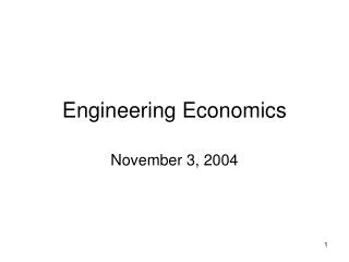
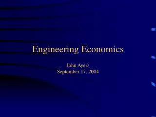
FOOD ENGINEERING DESIGN AND ECONOMICS. HEAT-EXCHANGER DESIGN. Heat Exchanger. m H in. m H out. Q. Considering the heat exchanger given in the figure the continuous, steady-state heat duty is given b y, Q=m (H out -H in ) where Q is the heat duty (rate of heat transfer)

E N D
FOOD ENGINEERING DESIGN AND ECONOMICS HEAT-EXCHANGER DESIGN
Heat Exchanger m Hin m Hout Q Considering the heat exchanger given in the figure the continuous, steady-state heat duty is given by, Q=m(Hout-Hin) where Q is the heat duty (rate of heat transfer) m is the flow rate of the stream (mass or molar) Hin is the enthalpy of the stream entering (per unit mass or mole) Hout is the enthalpy of the stream leaving (per unit mass or mole)
Heat is transferred to or from process streams using other process streams or “heat transfer media”. In a heat exchanger design, every effort is made to exchange heat between process streams and thereby minimize the use of heat transfer media (referred to as utilities). • Heat transfer media are classified as “coolants (heat sinks)” when heat is transferred to them from process streams, and as “heat sources” when heat is transferred from them to process streams.
The transport equation for heat exchange is expressed as; Q=UAΔTm Where, U is the overall heat transfer coefficient A is the area for heat transfer ΔTm is the mean temperature driving force for heat transfer countercurrent flow co current flow cross flow
Equipment for Heat Exchange Double Pipe Heat Exchangers A typical double pipe heat exchanger consists of an inner straight pipe of circular cross-section, concentric to and supported within an outer straight pipe by means of packing glands. One stream flows through the inner pipe, while the other stream flows counter currently through the annular passage between the outer wall of the inner pipe and the inner wall of the outer pipe. When one stream is at high temperature and/ or high pressure, and/or its corrosive, it is passed through the inner pipe. If the other stream is a gas, longitudinal fins can be added to the outside surface of the inner pipe to help balance the inner and outer heat transfer resistances. Double pipe heat exchangers are not recommended for use in boiling or vaporization services.
Shell and Tube Heat Exchangers Shell and tube heat exchangers, whose design is standardized by the Tubular Exchanger Manufacturers Association (TEMA) has changed little in past years and data for configuration and using details are well documented. Heat transfer area per unit volume is greatly increased by placing a large number of small diameter tubes inside a shell and many configurations are available. The most common configurations are 1 shell pass and 1 tube mass (1-1 exchanger); 1 shell pass and 2 tube passes (1-2 exchanger) and 2 shell pass and 4 tube passes (2-4 exchanger). Cross baffles are used so that the fluid is forced to flow perpendicular across the tube bank rather than parallel with it. This added turbulence generated by this cross flow increases the shell side heat transfer coefficient.
Plate and Frame Heat Exchangers When the two fluidsexchanging heat must be kept separate, plate and frame plate heat exchangers made of stainless steel are commonly used. A typical configuration consists of a series of pressed corrugated plates on close spacing. Hot and cold fluids flow on opposite sides of a plate. Heat transfer coefficients are high because of the enhancement of turbulence by the corrugations. Fouling of the surfaces is low and the heat transfer surfaces are readily cleaned. Because gasket seals are necessary in the grooves around the periphery of the plates to contain and direct the fluids, operating pressures and temperatures are limited to 300 psig and 4000F. Plate and frame units with as much as 16000ft2 of heat transfer surface area are available. These heat exchangers are suitable for heating and cooling with no phase change. They can be designed for very small minimum approach temperatures andare ideal for viscous, corrosive fluids.
Spiral Plate Heat Exchangers Heat transfer coefficients can also be enhanced by using spiral flow passageways as in the spiral plate heat exchangers. This unit provides true counter-current flow. Typically, the hot fluid enters at the center of the spiral and flows outward, while the cold fluid enters at the periphery and flows inward. The heat exchanger is competitive with the shell and tube heat exchanger for heating and cooling of highly viscous, corrosive, fouling and scaling fluids at ambient to moderate pressures. Units with up to 2000 ft2 of heat transfer surface area are available.
Plate Fin Heat Exchangers When sensible heat is to be exchanged between two gases, extended heat transfer surface in the form of fins is desirable on both sides. This is accomplished by plate-fin heat exchangers. These compact units achieve heat transfer surface areas of 350 ft2/ft3 of unit, which is much higher (up to 4 times) than for shell and tube heat exchangers. The fins consist of corrugated surfaces of 0.2 to 0.6 mm thickness and 3.8 to 11.8 mm height. Fin density is 230-700 fins/m. Plate fin units can be designed for high pressures and for countercurrent or cross flow. Two, three or more streams can exchange heat in asingle unit.
The rate of heat transfer between two streams flowing through a heat exchanger is governed by; Q=UAΔTm Except for a few simple, idealized cases, the mean temperature-driving force, ΔTm is a complicated function of the heat exchanger flow configuration and the thermodynamic and transport properties of the fluids. When a phase change occurs, an additional complication enters into its determination.
The simplest expression for ΔTm is determined when the following assumptions hold: • Stream flows are at steady state • Stream flows are countercurrent or co current o each other • The overall heat transfer coefficient is constant throughout the exchanger • Each stream undergoes only sensible enthalpy changes (heating or cooling), with constant specific heat • Heat losses are negligible The ΔTm is a function of the driving forces at the two ends of the exchanger.
To determine the heat transfer area of a heat exchanger an overall heat transfer is required.