Download
1 / 18
180 likes | 305 Views
This paper presents a novel digital background calibration technique for pipelined analog-to-digital converters (ADCs). The method utilizes least mean square (LMS) adaptive filtering to infer and correct component errors from conversion results, employing a low but precise ADC for performance. The proposed approach effectively addresses common calibration challenges, including capacitor mismatch and finite op-amp gain, simultaneously eliminating errors while maintaining the integrity of the analog signal path. This innovative method enhances throughput and resolution in high-performance ADC applications.

E N D
Paper 9:Y.Chiu et.al: “Least Mean Square Adaptive Digital Background Calibration of Pipelined Analog-to-Digital Converters”, IEEE Transactions on Circuits and Systems-I: Regular Papers, Vol. 51, No. 1, January 2004, pp 38-46
Y.Chiu et.al: “Least Mean Square Adaptive Digital Background Calibration of Pipelined Analog-to-Digital Converters” Outline: We present an adaptive digital technique to calibrate pipelined analog-to-digital converters. The new approach infers component errors from conversion results and applies digital postprocessing to correct those errors. With the help of a low, but accurate ADC, the proposed code-domain adaptive FIR filter is sufficient to remove the effect of component errors.
Y.Chiu et.al: “Least Mean Square Adaptive Digital Background Calibration of Pipelined Analog-to-Digital Converters” • Introduction • Pipeline ADC • High throughput and high resolution • Accuracy limited to about 10 bits without calibration. • Front-end T/H bandwith limitation, capacitor mismatch, finite opamp gain, charge injection... • Digital calibration techniques • Analog signal paths disturbed during calibration • Foreground calibration suffers from lack of tracking capability • ”Accuracy boot-strapping” • Calibration is performed stage-by-stage from LSB to MSB • Sequental operation cumbersome to implement, adds digital and analog overhead • This calibration technique • Treats errors analogous to distortion in communication channels • Errors from all stages removed simultaneously • The analog signal path is completely intact • Corrects dominant memory-less linear errors • Capacitor mismatch, finite opamp-gain, switch-induced offset errors
Y.Chiu et.al: “Least Mean Square Adaptive Digital Background Calibration of Pipelined Analog-to-Digital Converters” • Nonlinear channel model • Dynamic and static errors cause nonlinearity • Finite bandwidth and slew-rate introduce memory effects • Distortion • Capacitor mismatch, finite opamp-gain and charge injection introduces static errors • INL, DNL, offset, gain-error • ADC-model: • Decision vector: • D=[D1 D2.....DN]T • DK is decision from k’th stage • Weighting vector (1.5bit): • W=[2N-1 2N-2....20]T • Ideal ADC decision is thus: • Linear transformation of the code vector
Y.Chiu et.al: “Least Mean Square Adaptive Digital Background Calibration of Pipelined Analog-to-Digital Converters” • Nonlinear channel model: • A real ADC exhibits nonlinearity and memory effect. • How do we compensate? • Volterra filtering: • Of the digital output WTD • Correct decision can not be recovered when a multiple-to-one mapping from Vin to WTD occurs (e.g. Nonmonotonic codes) • High-order Volterra filter is very complex. • Non-linear transform: • The correct decision can be obtained by a non-linear transform of D • Analog errors modelled as a code-domain non-linear channel. • Still a form of Volterra-filter but the operand is vector D in lieu of the scalar WTD • Assume D as a sufficient statistic for Din=Vin/Vr, the quantized version of Vin, when quantization error is ignored.
Y.Chiu et.al: “Least Mean Square Adaptive Digital Background Calibration of Pipelined Analog-to-Digital Converters” • Code space and sufficient statistics: • Redundancy and error correction: • ”The final decision is not made until the last stage resolves where circuit nonidealities are negligible due to large residue gain accumulated.” • {DK} is a binary decomposition of Din. • {DK} fully span the code space of Din if no missing codes occur. • {DK} consequently represents a set of sufficient statistics for Din. • I.e. Dincan be fully recovered from {DK}, when quantization and circuit noise are ignored. • Not susceptible to nonmonotonicity as the Volterra filtering of WTD. • In the rest, we focus on the dominant, memoryless linear errors. • Capacitor mismatch, finite opamp-gain and switch-induced offsets.
Y.Chiu et.al: “Least Mean Square Adaptive Digital Background Calibration of Pipelined Analog-to-Digital Converters” • The LE approach: • Stage I-O transfer function: • Vr: Reference voltage • Vos: Input-ref. opamp offset • Cx: Virtual gnd parasitic cap. • d=0,1 or 2. • Rewrite: • Define Di=Vi/Vr, Do=Vo/Vr, Dos=Vos/Vr for digital representation:
Y.Chiu et.al: “Least Mean Square Adaptive Digital Background Calibration of Pipelined Analog-to-Digital Converters” • The LE approach: • Rewrite to simplify: • Applied to each stage in sequence, recursively, we get: • We can rewrite this to a sum of three terms: • This is a FIR-filter. • The first term (A) is the weighted sum of {DK} • The second term is quantization error • The third term is total input-referred offset.
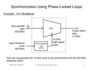
Y.Chiu et.al: “Least Mean Square Adaptive Digital Background Calibration of Pipelined Analog-to-Digital Converters” • The LE approach: • In reality, tap values are not known due to mismatch, finite gain and offset errors. • Adaptive techniques to obtain them on the fly • Steepest gradient descent adaptive digital background calibration scheme • The output vector D is decimated and applied to an adaptive digital filter. • A parallel slow-but-accurate ADC is used to obtain Din • The ADF tap values are updated using a least-mean-square algorithm driven by the error signal and the update is performed at the speed of the slow ADC.
Y.Chiu et.al: “Least Mean Square Adaptive Digital Background Calibration of Pipelined Analog-to-Digital Converters” • Simulations • 10-bit prototype • Adaption runs at the speed of the ADC (to decrease simulation time) • Slow-ADC has 16b output, pipeline has 12b output • nLMS-algorithm to update filter taps • Step-size µ=0.1 (0<µ<2 for stability).
Y.Chiu et.al: “Least Mean Square Adaptive Digital Background Calibration of Pipelined Analog-to-Digital Converters” • Simulation results
Y.Chiu et.al: “Least Mean Square Adaptive Digital Background Calibration of Pipelined Analog-to-Digital Converters” • Simulation results
Y.Chiu et.al: “Least Mean Square Adaptive Digital Background Calibration of Pipelined Analog-to-Digital Converters” • Simulation results • Steady-state MSE: • Memoryless linear errors can be fully removed when the quantization noise is negligible. • Simulations confirm this, steady-state MSE is close to 12 bit. • Noise enhancement: • LE suffers from a noise-enhancement problem when the noise spectrum is not flat. • Missing codes cause this and greatly enhances noise. • Increase the word length of the raw code, adding more stages. • Singularity: • Equations for least-squares formulation: • Solve for F subject to least-squares criteria, there Y is a vector of N+1 input samples. • If X is non-singular: • A set of N+1 noiseless observations of Din and D should yield enough information to determine N+1 unknown tap values. • The input signal does not have to exercise the whole input range for calibration to work.
Y.Chiu et.al: “Least Mean Square Adaptive Digital Background Calibration of Pipelined Analog-to-Digital Converters” • Simulation results • Singularity: • If Vin is confined to a range where D1(n) does not toggle for all N+1 samples, the D-matrix will be singular. • Solution still exists: • LMS or recursive least-squares (RLS) algorithm will still work. • However, it will find only a local optimum for the filter coefficients within this range. • Non-linear errors are not treated • Will need non-linear, i.e. Volterra, filtering. • Very complex. • Conclusions: • All-digital, adaptive, data-driven algorithm has been presented. • Based on theory for equalization of communications channels. • Corrects linear pipeline ADC errors • Capacitor mismatch, finite opamp-gain, input-referred offsets