Download
1 / 54
550 likes | 602 Views
Understand congestion control algorithms, the effects of congestion, and the importance of flow control. Learn about choke packets, hop-by-hop backpressure, and the leaky bucket concept in managing network traffic.

E N D
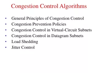
Congestion Control Algorithms AMRITPAL SINGH
Introduction • What is Congestion? • Congestion occurs when the number of packets being transmitted through the network approaches the packet handling capacity of the network • Congestion control aims to keep number of packets below level at which performance falls off dramatically • The network and transport layers share the responsibility for handling congestion.
Effects of Congestion • Packets arriving are stored at input buffers • Routing decision made • Packet moves to output buffer • Packets queued for output transmitted as fast as possible • If packets arrive too fast to be routed, or to be output, buffers will fill • Can discard packets • Can use flow control
Introduction • When the number of packets hosts send into the network is well within its carrying capacity, the number delivered is proportional to the number sent. • However, as the offered load approaches the carrying capacity, bursts of traffic occasionally fill up the buffers inside routers and some packets are lost. • Unless the network is well designed, it may experience a congestion collapse, in which performance fall as the offered load increases beyond the capacity.
Introduction • It is worth pointing out the difference between congestion control and flow control. • Congestion control has to do with making sure the network is able to carry the offered traffic. • Flow control, in contrast, relates to the traffic between a particular sender and a particular receiver.
Choke Packets • A specialized packet that is used for flow control along a network. • A router detects congestion by measuring the percentage of buffers in use, line utilization and average queue lengths. • When it detects congestion, it sends choke packets across the network to all the data sources associated with the congestion. • The sources respond by reducing the amount of data they are sending.
Choke Packets • When the source host gets the choke packet, it is required to reduce the traffic sent to the specified destination. • Example : An Internet Control Message Protocol (ICMP) source quench packet is a type of choke packet normally used by routers.
Hop-by-Hop Backpressure • If node becomes congested it can slow down or halt flow of packets from other nodes. • May mean that other nodes have to apply control on incoming packet rates • Propagates back to source.
Hop-by-Hop Backpressure • Used in connection oriented that allow hop by hop congestion control. • This technique is similar to back pressure in fluids flowing down a pipe. • When the end of pipe is closed, the fluid pressure backs up the pipe to the point of origin.
Hop-by-Hop Backpressure • If node 6 becomes congested, then node 6 can slow down or halt the flow of all packets from node 5 . • If this restriction persists, node 5 will need to slow down on its incoming links. • This flow restriction propagates backward to sources, which are restricted in flow of new packets into the network.
Leaky Bucket • Consider a Bucket with a small hole at the bottom, whatever may be the rate of water pouring into the bucket, the rate at which water comes out from that small hole is constant. • Once the bucket is full, any additional water entering it spills over the sides and is lost. • The same idea of leaky bucket can be applied to packets
Leaky Bucket • Conceptually each network interface contains a leaky bucket. And the following steps are performed: • When the host has to send a packet, the packet is thrown into the bucket. • The bucket leaks at a constant rate, meaning the network interface transmits packets at a constant rate. • Bursty traffic is converted to a uniform traffic by the leaky bucket. • In practice the bucket is a finite queue that outputs at a finite rate.
Leaky Bucket • This arrangement can be simulated in the operating system or can be built into the hardware. • Implementation of this algorithm is easy and consists of a finite queue. • Whenever a packet arrives, if there is room in the queue it is queued up and if there is no room then the packet is discarded
Leaky Bucket (Cont’d) Bucket
Leaky Bucket (Cont’d) Empty Bucket
Leaky Bucket (Cont’d) Bucket Hole
Leaky Bucket (Cont’d) Water Bucket Hole
Leaky Bucket (Cont’d) Constant rate stream of drips, all nicely spaced, periodic
Token Bucket • The leaky bucket algorithm described above, enforces a rigid pattern at the output stream, irrespective of the pattern of the input. • For many applications it is better to allow the output to speed up somewhat when a larger burst arrives than to loose the data. • Token Bucket algorithm provides such a solution. In this algorithm leaky bucket holds token, generated at regular intervals.
Token Bucket • Main steps of this algorithm can be described as follows: • In regular intervals tokens are thrown into the bucket. • The bucket has a maximum capacity. • If there is a ready packet, a token is removed from the bucket, and the packet is send. • If there is no token in the bucket, the packet cannot be send
Token Bucket • Figure shows the two scenarios before and after the tokens present in the bucket have been consumed. • In Fig. the bucket holds two tokens, and three packets are waiting to be sent out of the interface • Two packets have been sent out by consuming two tokens, and 1 packet is still left. • The token bucket algorithm is less restrictive than the leaky bucket algorithm, in a sense that it allows bursty traffic.
Token Bucket • However, the limit of burst is restricted by the number of tokens available in the bucket at a particular instant of time. • The implementation of basic token bucket algorithm is simple; a variable is used just to count the tokens. • This counter is incremented every t seconds and is decremented whenever a packet is sent. • Whenever this counter reaches zero, no further packet is sent out
(Cont’d) Incoming Tokens Incoming Packets To Network + 5 4 3 2 1
(Cont’d) Incoming Tokens Incoming Packets To Network + 1 5 4 3 2
(Cont’d) Incoming Tokens Incoming Packets To Network + 2 5 4 3 1
(Cont’d) Incoming Tokens Incoming Cells To Network + 5 4 3 2 1
(Cont’d) Incoming Tokens Incoming Cells X X To Network + 3 2 1 5 4
(Cont’d) Incoming Tokens Incoming Cells X X To Network + 3 2 1
Token Bucket (a) Token bucket holding two tokens, before packets are send out, (b) Token bucket after two packets are send, one packet still remains as no token is left
Open Loop • In open-loop congestion control, policies are applied to prevent congestion before it happens. • In these mechanisms, congestion control is handled by either the source or the destination.
Open Loop • Retransmission Policy • If the sender feels that a sent packet is lost or corrupted, the packet needs to be retransmitted. Retransmission in general may increase congestion in the network. • However, a good retransmission policy can prevent congestion. • The retransmission policy and the retransmission timers must be designed to optimize efficiency and at the same time prevent congestion.
Open Loop • Window Policy • The type of window at the sender may also affect congestion. • The Selective Repeat window is better than the Go-Back-N window for congestion control. • In the Go-Back-N window, when the timer for a packet times out, several packets may be resent, although some may have arrived safe and sound at the receiver. • This duplication may make the congestion worse.
Open Loop • Acknowledgment Policy • The acknowledgment policy imposed by the receiver may also affect congestion. • If the receiver does not acknowledge every packet it receives, it may slow down the sender and help prevent congestion. • Sending fewer acknowledgments means imposing less load on the network.
Open Loop • Discarding Policy • A good discarding policy by the routers may prevent congestion and at the same time may not harm the integrity of the transmission. • Admission Policy • An admission policy, which is a quality-of-service mechanism, can also prevent congestion in virtual-circuit networks. • A router can deny establishing a virtual circuit connection if there is congestion in the network or if there is a possibility of future congestion.
Closed Loop • Backpressure (already explained earlier in slide) • Choke Packet (already explained earlier in slide) • In implicit signaling, there is no communication between the congested node or nodes and the source. • The source guesses that there is a congestion somewhere in the network from other symptoms.
Closed Loop • For example, when a source sends several packets and there is no acknowledgment for a while, one assumption is that the network is congested. • Explicit Signaling • The node that experiences congestion can explicitly send a signal to the source or destination. • The explicit signaling method, however, is different from the choke packet method. • In the choke packet method, a separate packet is used for this purpose; in the explicit signaling method, the signal is included in the packets that carry data.
Closed Loop • Backward Signaling • A bit can be set in a packet moving in the direction opposite to the congestion. • Forward Signaling • A bit can be set in a packet moving in the direction of the congestion. This bit can warn the destination that there is congestion.
QOS • Quality of service (QoS) is an internetworking issue that has been discussed more than defined. • We can informally define quality of service as something a flow seeks to attain.
QOS • Jitter • Jitter is defined as the variation in the packet delay. • High jitter means the difference between delays is large; low jitter means the variation is small. • For example, if four packets depart at times 0, 1, 2, 3 and arrive at 20, 21, 22, 23, all have the same delay, 20 units of time. • On the other hand, if the above four packets arrive at 21, 23, 21, and 28, they will have different delays: 21,22, 19, and 24.
Techniques to improve QOS • Scheduling • Traffic Shaping • Resource Reservation • Admission Control
Techniques to improve QOS • Scheduling: FIFO Queuing