Download
1 / 23
230 likes | 358 Views
One Box Gunnery Trainer Final Design. Group 10 Anthony Muller Gerald Tyberghein Joshua Wood. Overview The Advanced Gunnery Trainer System The Pelican- Hardigg Case Product Specifications Concepts Selection Final Concept Design Analysis Tipping FEM Cost Possible Improvements

E N D
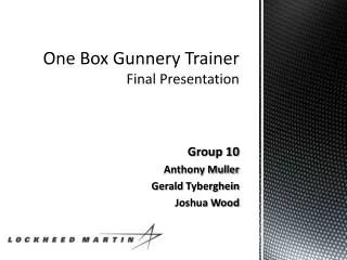
One Box Gunnery TrainerFinal Design Group 10 Anthony Muller Gerald Tyberghein Joshua Wood
Overview • The Advanced Gunnery Trainer System • The Pelican-Hardigg Case • Product Specifications • Concepts • Selection • Final Concept Design • Analysis • Tipping • FEM • Cost • Possible Improvements • Next Semester
The Advanced Gunnery Trainer System (AGTS) • Compact, cost efficient tabletop system • Used to sustain precision gunnery skills at all levels • Provides training procedures, basic skills, and drills • Can be linked together with other AGTSs Figure 1: Lockheed Martin TAGTS Source(www.lockheedmartin.com)
The Pelican-Hardigg Case Figure 3: Dual lid case opened to show rack Source: (www.pelican.com) Figure 2: Pelican-Hardigg case in military use Source: Pelican-Hardigg Case (www.pelican.com) Figure 4: Wheel transport Source: (www.pelican.com)
Product Specifications • Weighs less than 120 lbs • Gunner handle and monitor mounted in correct tactical position • Equipment must be safe when being transported • Packing does not interfere with components’ cooling • System must be stable (15 degree tip) • System must be durable • Easy to set up Figure 5: Current TAGTS setup Source: Payne, Jeffrey
Main Concepts Figure 6 : Tabletop, Box on Floor, Hybrid Concepts.
Selection Matrix Table 1: Selection Matrix for 3 Concepts
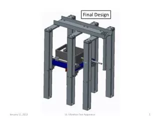
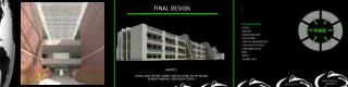
Finalized Concept Figure 7 : Case Packed Position Figure 8 : Side View Inside Case
Satisfying Weight Specification Case weight : 52 lbs Components’ total weight : 40 lb Mounting equipment’s weight : 15 lbs Miscellaneous hardware weight : 5 lbs Total weight : 112lbs Product specification weight : Under 120 lbs
Satisfying Correct Mounting Position and Ease of Assembly Specifications Figure 9: Person Using TAGTS
Satisfying Stability Specification: Maximum Input Force Analysis Figure 10 : Force Distribution of Deployed System
Tip Analysis • Set left side normal force equal to 0, to assume tipping. • Take moments about right side normal force, and solve for the input force on the handle. • 112lbs(8.62in) – F(16.67in) = 0 • Maximum applied downward force on handle • F = 58 lbs
Satisfying Stability Specification: Maximum Tip Angle Analysis Figure 11 : Maximum Angle of Deployed System
Tip Analysis • Tipping occurs when left normal force is equal to 0 and center of gravity passes the right normal force. • Solving for this angle, theta=atan(8.62/8.3) = 46deg • Product specification: Satisfy 15 degree tip rule
Satisfying Transportation Safety : MIL-STD-810 Test • “…a generally accepted standard of ruggedisation for testing and compliance for mobile computers and equipment.” (Secure Systems and Technologies) • Mechanical Shock • Random Mechanical • Vibration • Altitude Figure 12 : Vibration Test Source: Qualtest (www.qualtest.com)
Satisfying Durability Specification: Shock Mounts • For our case model: • Shock mounts rated for • 50-70G fragility • Provide shock and vibration dampening for systems weighing 20-200lbs • Provides cooling airflow Figure 13 : View of Shock Mounts Source: Pelican-Hardigg Case (www.pelican.com)
FEM Analysis Lbm/(in sec^2) Figure 14 : Stress Distribution of von Mises
FEM Analysis Lbm/(in sec^2) Figure 15 : Stress Distribution of the Maximum Principle Stresses
Cost Analysis Table 2 : Cost Analysis
Possible Improvements • Add attachable legs to increase • portability • Utilize touchscreen to eliminate • mouse and keyboard • Incorporate handle design from Senior Design Team 9 to allow for other vehicle simulations Figure 16 : Pelican Legs Source:(www.pelican.com)
Next Semester… • Install mounting equipment into Pelican case • Machine mockup components to mount in case to test • Visit General Dynamics Lab Systems • Visit Qual Test Labs to run tests and analyze results • Bring system to Lockheed Martin to implement real components in case and run tests.
References Lockheed Martin. The Advanced Gunnery Trainer System (AGTS) Tabletop Trainer. Lockheed Martin. Www.lockheedmartin.com. Web. 31 Oct. 2010. Pelican. Pelican Hardigg Cases. Pelican, 2010. Www.pelican.com. Web. 03 Nov 2010. Qualtest. Www.qualtest.com/index. Web. 10 Nov 2010 Secure Systems and Technologies. MIL-STD-810 Overview. Secure Systems and Technologies. http://www.sst.ws/images/downloads/MIL-STD-810%20overview%20iss%205.pdf. Web. 31 Oct. 2010.
Acknowledgements Sponsor – Lockheed Martin - Jeffrey Payne (Mechanical Engineer) Sponsor – Pelican Hardigg - DariaBoley (Pelican Hardigg Salesperson) Advisors – - Dr. Rob Hovsapian - Dr. Patrick Hollis - Dr. SrinivasKosaraju - Ms. Shannon Ingersoll - Mr. Joseph Trpisovsky