ILC Control and IHEP Activity
250 likes | 409 Views
ILC Control and IHEP Activity. Jijiu. Zhao, Gang. Li IHEP, Nov.5 ~7,2007 CCAST ILC Accelerator Workshop and 1st Asia ILC R&D Seminar under JSPS Core-University Program. Introduction.

ILC Control and IHEP Activity
E N D
Presentation Transcript
ILC Control and IHEP Activity Jijiu. Zhao, Gang. Li IHEP, Nov.5~7,2007 CCAST ILC Accelerator Workshop and 1st Asia ILC R&D Seminar under JSPS Core-University Program
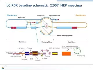
Introduction • The International Linear Collider (ILC) is a 200- to 500-GeV center-of-mass high-luminosity linear electron-positron collider, based on 1.3-GHz superconducting radio frequency accelerating cavities. • The machine operates at a pulse repetition rate of 5-Hz, with each 1-ms beam pulse comprising ~3000 bunches.
Introduction (cont’) • The control system overall design is evolving as details of the accelerator technical design are developed. • The Control System Reference Design serves these purposes: • Establish afunctionaland physical model for costing purposes • Establish a starting point for engineering design and R&D efforts • Communicate our vision of the control system
Computing Infrastructure Computer Center Business Computing Computing Networks Desktop Support Engineering Support Computer Security Management Controls System Central Computers On Site Control Room Controls Services Operator Interface Automation Logging databases Data Archival Alarms Diagnostics Interfaces to Technical Systems Front Ends Hardware software Cabling ATCA High Availability LLRF Controls Beam Feedback System Protection Systems Machine Protection Personnel Protection Beam Containment Network Infrastructure Assembly and Testing of Controls Racks Scope of Controls
Requirements of Controls • High Availability • Controls System allocation • 2500 hours MTBF (Mean Time Before Failure) • 5 hours MTTR (Mean Time To Repair) • 15 hours downtime per year • CS availability – 99% to 99.9% • Each system 99.999% available • Standardization • Diagnostic Layer • Scalability • ~100,000 devices should be controlled, millions of control points • Automation • Sequencing, automatic startup, tuning, etc. • Slow and Fast Beam Based Feedback • Timing and Synchronization • Precision RF Phase References • 0.1% amplitude & 0.1 degree phase stability • Remote Operation • Enable Collaborators to participate more fully
Functional Model • Client Tier • GUIs • Scripting • Services Tier • “Business Logic” • Device abstraction • Feedback engine • State machines • Online models • … • Front-End Tier • Technical Systems Interfaces • Control-point level
Functional Model (cont’) • Client Tier: • Provides applications with which people directly interact. Applications range from engineer-oriented control consoles to high-level physics control applications to system configuration management. • Engineer-oriented consoles are focused on the operation of the underlying accelerator equipment. • High-level physics applications require a blend of services that combine data from the front-end tier and supporting data from the relational database in the context of high-level device abstractions (e.g, magnets, BPMs)
Functional Model (cont’) • Services Tier: • Provides services that coordinate many activities while providing a well-defined set of public interfaces (non-graphical). • Device abstractions such as magnets and BPMs that incorporate engineering, physics, and control models are represented in this tier. • This makes it possible to relate high-level machine parameters with low-level equipment settings in a standard way. For example, a parameter save/restore service can prevent two clients from simultaneously attempting to restore a common subset of operational parameters. • This centralization of controls system provides many benefits in terms of coordination, conflict avoidance, security, and optimization.
Functional Model (cont’) • Front-end Tier: • Provides access to the field I/O and underlying dedicated fast feedback systems. • This tier is configured and managed by the services tier, but can run autonomously. • For example, the services tier may configure a feedback loop in the front-end tier, but the loop itself runs without direct involvement. • The primary abstraction in this tier is a channel, or process variable, roughly equivalent to a single I/O point.
Physical Model (cont’) • The ILC control system must reliably interact with more than 100,000 technical system devices that could collectively amount to several million scalar and vector Process Variables (PVs) distributed across the many kilometers of beam lines and facilities at the ILC site. • Information must be processed and distributed on a variety of timescales from microseconds to several seconds. • The overall philosophy is to develop an architecture that can meet the requirements, while leveraging the cost savings and rapid evolutionary advancements of commercial off-the-shelf (COTS) components.
Network Infrastructure • Data collection, issuing and acting on setpoints, and pulse-to pulse feedback algorithms are all synchronized to the pulse repetition rate. • The controls network must be designed to ensure adequate response and determinism to support this pulse-to-pulse synchronous operation, which in turn requires prescribing compliance criteria for any device attached to this network. • Additionally, large data sources must be prudently managed to avoid network saturation. • Dedicated compute nodes associated with each backbone network switch service for monitoring, data reduction, and implementing feedback algorithms.
Network Infrastructure (cont’) • BCD Control Room Cluster Architecture
ILC test facility and collaboration • Several accelerator facilities are used as the part of the ILC test facilities in the wide world: • LLRF: Fermilab, DESY, KEK, SNS, LBNL, U.Penn and others • ATCA: DESY is developing a version of their LLRF Simcon board on ATCA, and several other institutions worldwide are beginning to explore ATCA, such as SLAC. • Beam Instrumentation: Fermilab, SLAC, KEK, DESY, U.Oxford, U. London and others. • Goal: • The ILC Control work is highly collaborative, and several work packages overlap between institutions. • Researching and Working on the facility to assess the cost and solve the key technique of ILC Controls.
IHEP Activity • ATCA (Advanced Telecom Computing Architecture) is chosen as the Electronics platform of ILC controls. • Unique open standard designed specifically for 0.99999 (5-9’s) availability at the crate level • Core components available from industry • Crates with intelligent platform management of power, module type & ID, load shedding & re-routing • N+1 redundancy options for core controllers, communication, power, cooling fans • All serial multi-gigabit communications by wire for short distance or fiber for long distance • Controllers, switches and high performance processors • Ideal for core of controls system
IHEP Activity (cont’) • Now, IHEP Control Group get budget support. • Plan to set up a prototype of ATCA at the lab. • Do some work at ATCA platform as follows: • Study performance of ATCA including shelf-manager, redundancy switcher and power supply, etc. • Install the EPICS into ATCA system. • Research and test the EPICS HA at ATCA. • etc.
Research field: IHEP Activity (cont’) • ATCA HA • Xen technology • Linux HA • EPICS HA Shelf Management Dual Xeon processors Fig. the prototype of the ATCA Switch
Xen Technology IHEP Activity (cont’) • XenSource company • A open source virtual machine monitor (VMM), or hypervisor, for the x86 processor architecture • Can securely execute multiple virtual machines on a single physical system with close-to-native performance • Live migration of running virtual machines between physical hosts • Xend: a daemon responsible for managing virtual machines and providing access to their consoles
LinuxHA IHEP Activity (cont’) • Putting together a group of computers that trust each other to provide a service even when system components fail • When one machine goes down, others take over its work • This involves IP address takeover, service takeover, etc. • New work comes to the “takeover” machine • Not primarily designed for high performance • It cannot achieve 100% availability – nothing can • HA Clustering designed to recover from single faults
IHEP Activity (cont’) • EPICS HA can be completed via two methods: one is Xen technology and the other is Linux HA. Fig1 EPICS HA structure via Xen Fig2 EPICS HA structure via Linux HA
IHEP Activity (cont’) Go on: • Study EPICS HA via HA middleware: OpenClovis or Goahead. Fig3 EPICS HA structure via OpenClovis or Goahead
IHEP Activity (cont’) Conclusion: • Accumulate more experience based on the prototype of the ATCA system. • Hope researching results of ATCA be used into ILC test facilities as soon as possible and contribute to the assessment of ILC control system. • Improve and strengthen the close cooperation with the other ILC control teams in the world.
Thanks for your attention! Some information of this report is referred to ILC control kick-off meeting, Aug 20~22,2007.