Understanding Control Unit Microoperations in Digital Computers
The control unit of a digital computer is organized through registers and microoperations. Microoperations are elementary operations performed on data in registers during a clock pulse, encompassing functions like shift, load, and clear. A register transfer language specifies these operations symbolically, enabling clear expression of data movement between registers. Registers are often named based on their functions, such as MAR for memory address register and PC for program counter. Through controlled signals, specific actions occur conditionally, driving operations in a synchronized manner.

Understanding Control Unit Microoperations in Digital Computers
E N D
Presentation Transcript
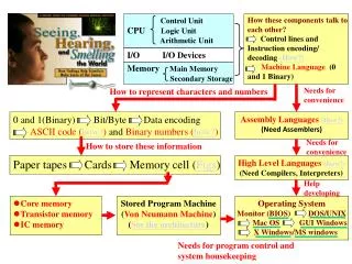
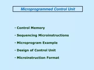
The internal hardware organization of a digital computer is best defined by specifying. • The set of registers it contains and their functions. • The sequence of microoperations performed on the binary information stored. • The control that initiates the sequence of microoperations.
Microoperation • The operations on the data in registers are called microoperations. • The functions built into registers are examples of microoperations • Shift, Load, Clear, Increment, … An elementary operation performed (during one clock pulse), on the information stored in one or more registers
Use symbols, rather than words, to specify the sequence of microoperations Register transfer language: • The symbolic notation used to describe the microoperation transfer among registers • Number of microoperations required to execute an instruction by a processing unit • A register transfer language enables proper expressions for these microoperations
Registers • Registers are designated by capital letters, sometimes followed by numbers (e.g., A, R13, IR) • Often the names indicate function: • MAR - memory address register • PC - program counter • IR - instruction register • Registers and their contents can be viewed and represented in variousways • A register can be viewed as a single entity: • Registers may also be represented showing the bits of data they contain MAR
Declare Registers Declare registers A [8], B [8] PC [16] PCHI [8] = PC[15 – 8] B [0] A [8]
Register Transfer • Copying the contents of one register to another is a register transfer • A register transfer is indicated as R2 R1 • In this case the contents of register R1 are copied (loaded) into register R2 • A simultaneous transfer of all bits from the source R1 to the destination register R2, during one clock pulse • Note that this is a non-destructive; i.e. the contents of R1 are not altered by copying (loading) them to R2
Register Transfer • A register transfer such as A B Implies that the digital system has • the data lines from the source register B to the destination register A • Parallel load in the destination register A • Control lines to perform the action B 8 Data A E
Control Function • Often actions need to only occur if a certain condition is true • This is similar to an “if” statement in a programming language • In digital systems, this is often done via a control signal, called a control function • If the signal is 1, the action takes place • This is represented as: P: R2 R1 Which means “if P = 1, then load the contents of register R1 into register R2”, i.e.,if (P = 1) then (R2 R1)
Hardware Implementation of Controlled Transfer Implementation of controlled transfer P: R2 R1 Block diagram Load P Control Circuit R2 Clock n R1
i.e., C0 : A B where C0 = G ᴧ D [0]1 If A > B and D[0] = 0 then A B B 8 D[0] Enable A>B B G A A
If x = 0 and t = 1 then A B else A D i.e., C0 : A B C01 : A D Where C0 = x1t and C01=(x1t)1 B D C0 0 1 MUX X t A Vcc
Simultaneous Operations • If two or more operations are to occur simultaneously, they are separated with commas P: R3 R5,MAR IR • Here, if the control function P = 1, load the contents of R5 into R3, and at the same time (clock), load the contents of register IR into register MAR
Bus Transfer In RTL • Depending on whether the bus is to be mentioned explicitly or not, register transfer can be indicated as either or • In the former case the bus is implicit, but in the latter, it is explicitly indicated R2 R1 BUS R1, R2 BUS
SUMMARY OF R. TRANSFER MICROOPERATIONS D A Transfer content of reg. A into reg. D A A+1 Increment the content of A by 1 A A -1Decrement the content of A by 1 A1 + 1 Compute the 2’s complement of A D A ᴠ BCompute the logical OR of A and B and save the result in D D A ᴧ BCompute the logical AND of A and B and save the result in D LSR (A) Logically shift the contents of the register A one position to the right . ASR (A)Arithmetically shift the contents of the register A one position to the right .
LSL • ASL • ROR • ROL • $ • ASR(A$Q) • ; • , • M inbus
Declare registers A[8], M[8], Q[8]; Declare buses Inbus[8], Outbus[8] Start: A 0, M Inbus;clear A and transfer M Q Inbus ; transfer Q Loop: A A+M, Q Q – 1; If Q <> 0 then go to Loop; Outbus = A Halt: Go to Halt
MBR RWM Unit MAR R (Read Control) W (write Control) MBR R: MBR M ( MAR) W: M ( MAR) MBR