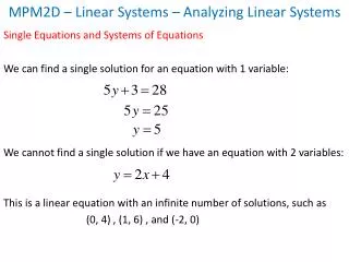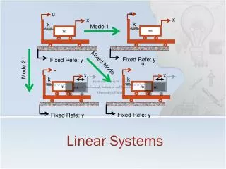
Linear Systems
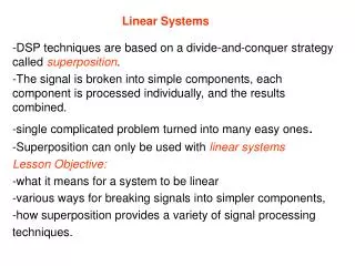
Linear Systems. -DSP techniques are based on a divide-and-conquer strategy called superposition . -The signal is broken into simple components, each component is processed individually, and the results combined. -single complicated problem turned into many easy ones .


Linear Systems
E N D
Presentation Transcript
Linear Systems -DSP techniques are based on a divide-and-conquer strategy called superposition. -The signal is broken into simple components, each component is processed individually, and the results combined. -single complicated problem turned into many easy ones. -Superposition can only be used with linear systems Lesson Objective: -what it means for a system to be linear -various ways for breaking signals into simpler components, -how superposition provides a variety of signal processing techniques.
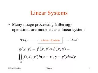
Signals and Systems Basic definition • A signal shows how one parameter varies with another parameter. e.g. sound level vs. time. • A system is any process that produces an output signal in response to an input signal. e.g. a block box or a computer program Radar Cell phone EKG
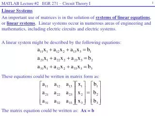
what properties make a system linear? A system is called linear if it has two mathematical properties: homogeneity (hÇma-gen-~-ity) and additivity also shift invariance(there are exceptions) Homogeneity R in Ohms law A system is homogeneous if an amplitude change in the input results in an identical amplitude change in the output.
shift invariance a shift in the input signal will result in nothing more than an identical shift in the output signal. when s= - 2, the signal is shifted right by two samples.
sinusoidal fidelity An important characteristic of linear systems is how they behave with sinusoids, a property called sinusoidal fidelity: If the input to a linear system is a sinusoidal wave, the output will also be a sinusoidal wave, and at exactly the same frequency as the input Note: a square wave entering a linear system will not produce a square wave on the output.
Examples of Linear Systems Wave propagation such as sound and electromagnetic waves • Electrical circuits composed of resistors, capacitors, and inductors • Electronic circuits, such as amplifiers and filters • Mechanical motion from the interaction of masses, springs, and dashpots (dampeners) • Systems described by differential equations such as resistor-capacitor-inductor • networks • Multiplication by a constant, that is, amplification or attenuation of the signal • Signal changes, such as echoes, resonances, and image blurring • The unity system where the output is always equal to the input • Differentiation and integration, and the analogous operations of first difference and • running sum for discrete signals • Small perturbations in an otherwise nonlinear system, for instance, a small signal being amplified by a properly biased transistor • Convolution, a mathematical operation where each value in the output is expressed as the sum of values in the input multiplied by a set of weighing coefficients. • Recursion, a technique similar to convolution, except previously calculated values in the output are used in addition to values from the input
Examples of Nonlinear Systems • Systems that do not have static linearity, for instance, the voltage and power in a resistor: , the radiant energy emission of a hot object depending on its temperature: P’= V2R • Systems that do not have sinusoidal fidelity, such as electronics circuits for: peak detection, squaring, sine wave to square wave conversion, frequency doubling, etc. • Common electronic distortion, such as clipping, crossover distortion and slewing • Multiplication of one signal by another signal, such as in amplitude modulation and automatic gain controls • Hysteresis phenomena, such as magnetic flux density versus magnetic intensity in iron, or mechanical stress versus strain in vulcanized rubber • Saturation, such as electronic amplifiers and transformers driven too hard • Systems with a threshold, for example, digital logic gates,
Special Properties of Linearity Linearity is commutative, When two or more linear systems are arranged in a cascade, the order of the systems does not affect the characteristics of the overall combination.
Superposition: the Foundation of DSP In synthesis, two or more signals are added to form another signal. Decomposition is the opposite process, breaking one signal into two or more additive component signals.
The fundamental concept in DSP. Any signal, such as , can be decomposed into x [n]a group of additive components, shown hereby the signals: and . Passing x1[n], x2[n], x3[n]these components through a linear system produces the signals, and . y1[n], y2[n], y3[n]The synthesis (addition) of these output signals forms , the same signal produced y [n]when is passed through the system. Impulse decomposition
Impulse Decomposition Breaks an N samples signal into N component signals, each containing N samples. Each of the component signals contains one point from the original signal, with the remainder of the values being zero By knowing how a system responds to an impulse, the system's output can be calculated for any given input. Using convolution
Impulse Decomposition An N point signal is broken into N components, each consisting of a single nonzero point.
Fourier Decomposition Fourier decomposition is very mathematical and not at all obvious.. Any N point signal can be decomposed into N +2 signals, half of them sine waves and half of them cosine waves. The lowest frequency cosine wave (called in this xC0 [n] illustration), makes zero complete cycles over the N samples, i.e., it is a DC signal. The next cosine components: , , and , make 1, 2, xC1 [n] xC2 [n] xC3 [n] and 3 complete cycles over the N samples, respectively. This pattern holds for the remainder of the cosine waves, as well as for the sine wave components. Since the frequency of each component is fixed, the only thing that changes for different signals being decomposed is the amplitudeof each of the sine and cosine waves.
Fourier decomposition is important for three reasons First, a wide variety of signals are inherently created from superimposed sinusoids. Like Audio signals . Fourier decomposition provides a direct analysis of the information contained in these types of signals. Second, linear systems respond to sinusoids in a unique way: a sinusoidal input always results in a sinusoidal output. In this approach, systems are characterized by how they change the amplitude and phase of sinusoids passing through them. Since an input signal can be decomposed into sinusoids, knowing how a system will react to sinusoids allows the output of the system to be found. Third, the Fourier decomposition is the basis for a broad and powerful area of mathematics called Fourier analysis, and the even more advanced Laplace and z-transforms. Most cutting-edge DSP algorithms are based on some aspect of these techniques.
Fourier decomposition. cosine sine. An N point signal is decomposed into N+2 signals, each having N points. Half of these signals are cosine waves, and half are sine waves.