Download
1 / 14
140 likes | 233 Views
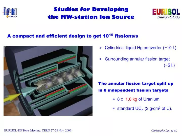
Studies for Developing the MW-station Ion Source. A compact and efficient design to get 10 15 fissions/s Cylindrical liquid Hg converter (~10 l.) Surrounding annular fission target (~5 l.) The annular fission target split up in 8 independent fission targets

E N D
Studies for Developingthe MW-station Ion Source A compact and efficient design to get 1015 fissions/s Cylindrical liquid Hg converter (~10 l.) Surrounding annular fission target (~5 l.) The annular fission target split up in 8 independent fission targets 8 x 1,6 kg of Uranium standard UCX (3 g/cm3 of U).
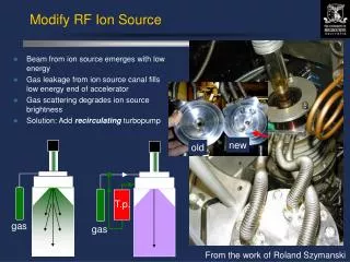
Overall issues • How to connect ion source to such a target system? • Multiple ion sources? Acceptable for the design of radioactive beam line? • Multiple transfer lines? Cf. Thierry STORA’s presentation. • What kind of ion source? • Capable of operating under the vapour from the bulky target. • Capable of withstanding the level of radiation generated close to the target.
target ion source PIS Ctransfer Ptarget [UC2 @ 2000 °C] ~10-5 mbar Basic scheme Corifice Q = C x ∆P with C order of 1 l/s. (molecular flow) ~10-6 < PIS < ~10-5 mbar Qout < ~10-5 mbar.l/s (negligible) PIS ~ Ptarget If no specific device on transfer line, most target out-gassing goes into the ion source.
Vapour from the fission target Considering a piece of 1/8 target (1,6 kg of nat.U): • Overall radioactive nuclei production ~1016 nuclei/s in target; if 10% released ~1015 nuclei/s ⇔~10-4 mbar.l/s • Stable out-gassing UC2 out-gassing is dominant (x100 larger than Ta out-gassing); Target surface at least x10 wider than standard >10-1 mbar.l/s (equilibrium) only a part reaches the ion source.
ion source position What kind of ion source? • Target out-gassing surface is a few x10 wider than standard • for efficient ion sources (εion ~ 1%):total extracted beam ~mA • Ion source close to the target 1014 neutrons/cm2/MW of beam A. Herrera-Martinez et al.
What about ECRIS? • OK for operating with such out-gassing conditions • Possibility of transfer-line cooling to reduce metal vapours • RF injection issue • Radiation damage of magnetic confinement system: • Possibility of using coils instead of permanent magnets • Radiation damage of insulators? e.g. glass fibres ~10 MGy Such studies are in progress for SPIRAL-2…
FEBIAD-type Ion Source? • Not dedicated for operating with high vapour flow: • Standard FEBIAD operate up to 10-3 mbar.l/s • EBGP (radial type, by J.M. Nitschke) up to 10-4 mbar.l/s • Nielsen and Nier-Bernas ion sources can operate: • e.g. beams of a few mA with an emittance of 20 π.mm.mrad @ 40 kV. • But quick wearing of the cathode. • Radiation damage of the refractory insulators • {cathode/anode} need of refractory insulators close to ionization chamber.
IRENA prototype Main features: • Minimum of components (no magnet!) • Insulators away from the ion. chamber • Radial cathode more reliable • Cathode Design • hazard of cathode/anode short • residual pressure in chamber • strong e- emisssion required IRENA prototype based on EBGP (Nitschke, LBL 1985).
IRENA 1st prototype: First results (1) Optimal conditions not yet reached: ionization efficiency (Kr): 0.03 % @ 2.10-5 mbar. Tests interrupted in March 06; to be pursued with a prototype supplied by NIPNE.
IRENA 1st prototype: First results (2) Total beam extracted @ 10-5 mbar as function of cathode heating. Total beam intensity comparable to EBGP (~µA) expected by 2000 °C within these operation conditions.
Optimizing IRENA design Increasing e- emission by 103 to get a prototype working with MW-target out-gassing. Another cathode material or cathode surface x103 (the ionization chamber may reach the typical size of ECRIS) Further studies using IES Lorentz code planned in 2007. Ph.D thesis M. Cheikh Mhamed
What about RILIS? • High pressure in the hot cavity • Larger production of non-selected positive ions • Deterioration of the plasma conditions in the cavity • Possible remedy • Increasing cavity diameter (keeping /L2 ~ constant) larger conductance and larger surface for increasing e- emission. • Changing cavity material to increase e- emission. • Or…
a plasma confinement structure Using IRENA radial structure with low voltage to generate lots of radial electrons only for confinement
Resume • Important to minimize target size as much as possible Cf. also D. Ridika’s poster • To get beams from Multi-MW target, many aspects have to be considered: specification on transfer tube, beam extraction, beam contamination etc. • Some possibilities for developing MW-station ion sources but requires important R&D works need for support Acknowledgment: Many thanks to all collaborators, special thanks to R. Catherall, V. Fedoseev, A. Herrera-Martinez, Y. Kadi, J. Lettry, D. Ridikas, T. Stora, F. Wenander)