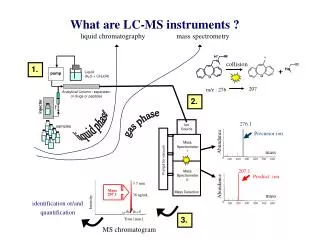
Ion Source Development at RAL
This document summarizes the key discussions and developments presented by Dan Faircloth and colleagues at the RAL Proton Meeting on March 24. It covers the latest advancements in proton ion source technologies, including the Penning H- ion source, surface plasma source, and Dudnikov type sources. Technical details highlight operational efficiencies of cesium vapor heating, negative ion beam extraction techniques, and modifications for improved discharge duty cycles. The collaborative efforts showcased involve a range of experts pushing the boundaries of ion source performance and diagnostics.

Ion Source Development at RAL
E N D
Presentation Transcript
Ion Source Development at RAL Dan Faircloth Including the work of: Scott Lawrie, Alan Letchford, Christoph Gabor, Phil Wise, Mark Whitehead, Trevor Wood, Mike Perkins, Mick Bates, David Findlay, Juergen Pozimski, Simon Jolly, Pete Savage, David Lee Dan Faircloth – Proton Meeting RAL Thursday 24th March
The ISIS Ion Source • Penning H- ion source • Surface plasma source (SPS) • Dudnikov type • 15 ml/min H2 • 3 g/month Cs • 20 day average lifetime
Negative Ion Beam Extraction Electrode Slit Aperture Plate Penning Pole Pieces Discharge Region Hollow Anode Air Cooling Channels Source Body Cathode Ceramic Spacer Mica Copper Spacer Mounting Flange 10mm Water Cooling Channels
Negative Ion Beam +17 kV Extraction Voltage Caesium Vapour Heated Transport Line 50 A Discharge Caesium Oven Piezo Hydrogen Valve Hollow Anode 10 mm H2
Negative Ion Beam +17 kV Extraction Voltage Caesium Vapour Heated Transport Line 50 A Discharge Caesium Oven Piezo Hydrogen Valve Source Runs at 50 Hz Rep Rate Hollow Anode 10 mm H2
H2 Gas Pulse ~ 200 μs Timing Discharge Pulse ~ 600 μs Extraction Voltage Pulse ~ 250 μs H- Beam Time Source Runs at 50 Hz Rep Rate
Heated Caesium Transport Line Hollow Anode Cathode Hydrogen Feed Air Cooling Discharge Power Feed Source Body Thermocouples
Extraction Mount Extraction Electrode Support Insulators Caesium Shields
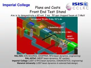
3 Sources at ISIS Operational Source 24 x 7 operation 20 day average lifetime 200-300 μs pulse length 50 Hz 35 keV 35 mA @ RFQ FETS Source Experimental sources High current Long pulse 65 keV Ion Source Development Rig Pre-test operational sources Problem solving
FETS 65 kV high voltage platform
Ion Source Diagnostics Vessel Laser 3 Solenoid LEBT
65 kV Platform DC power supply Platform ground - + - 18 kV Pulsed extraction power supply 160 MΩ 750 kΩ Extraction gap Aperture plate P.S. Extraction electrode + Protection electrode Extraction electrode, coldbox and sector magnet all pulsed Laboratory ground Coldbox H- beam 90 Sector magnet Toriod 1 Ground plane Suppression electrode Post extraction acceleration gap FETS Source Schematic
FETS Source Dan Faircloth – ICIS 2009
1. Extend discharge duty cycle Finite Element Modelling Transient Calculation 600 520 440 360 280 200 Cathode Surface ΔT= 73 ºC Steady state calculation ΔT= 39 ºC Anode Surface 2.2 ms discharge at 50 Hz achieved with simple design changes Computational fluid dynamic cooling calculation FETS source modifications
1. Extend discharge duty cycle 2. Discharge current Experiments For each extraction condition there is a range of discharge currents that give minimum beam divergence 14 kV extraction voltage 2.2 mm extraction gap FETS source modifications
1. Extend discharge duty cycle 3. Permanent magnet Penning field 2. Discharge current B Nd2Fe14B Permanent Magnets To allow different extraction voltages the Penning field must be decoupled from the sector magnet field Permanent magnets are used to produce the produce the 0.15 – 0.25 T required for a stable discharge FETS source modifications
1. Extend discharge duty cycle 3. Permanent magnet Penning field 2. Discharge current 4. Extraction Voltage, Geometry and Meniscus Widen plasma electrode aperture Increase voltage from 17 to 25 kV Child-Langmuir 78 mA Meniscus Studies FETS source modifications Decrease extraction jaw separation
1. Extend discharge duty cycle 3. Permanent magnet Penning field Magnet Redesign Beam expands under space charge Dipole has a focusing component Exact degree of compensation unknown 2. Discharge current 4. Extraction Optimum field gradient index n = 1.2 determined by experiment Field gradient index Size of good field region increased Field must be adequately terminated 0 0.5T Significant improvement in emittance Magnetic Field Gradient Index, n 5. Analysing magnet FETS source modifications
55.0 mm PA Gap 0.2 kVmm-1 0.3 kVmm-1 0.4 kVmm-1 0.5 kVmm-1 Increasing Post Acceleration Gap Length 9.2 mm PA Gap 1.2 kVmm-1 1.8 kVmm-1 2.1 kVmm-1 2.7 kVmm-1 2.5 mm PA Gap 4.4 kVmm-1 6.8 kVmm-1 7.6 kVmm-1 10 kVmm-1 2.0 mm PA Gap 5.5 kVmm-1 8.5 kVmm-1 9.5 kVmm-1 12.5 kVmm-1 11 kV PA Voltage 17 kV PA Voltage 19 kV PA Voltage 25 kV PA Voltage Increasing Post Acceleration Voltage Constant 10 kV Extraction Voltage 23 mA H- Beam Current Measured 355 mm from Ground Plane of PA Gap 1. Extend discharge duty cycle 3. Permanent magnet Penning field Optimize Post Acceleration Gap 2. Discharge current 4. Extraction 6. Post acceleration Minimum emittance growth occurs for a post acceleration field of 9 kVmm-1 5. Analysing magnet FETS source modifications
2000 Ls-1 Turbo Pump Laser Diagnostics Slit-slit scanners Toroid 1 400 Ls-1 turbo pump Solenoid 3 Solenoid 2 7×10⁻⁶mBar 5×10⁻⁶mBar Camera 1×10⁻⁴mBar 6×10⁻⁵mBar Toroid 2 Isolating Column Toroid3 Beam shutter Retractable Faraday Cup Solenoid 1 Pepper pot or profile scintillator head Differential pumping and laser profile vessel Diagnostics vessel Toroid 4 4 × 800 Ls-1 & 1 x 400 Ls-1 Turbo Pumps
Short Pulse Operation <1ms For pulse lengths shorter than 1 ms: 80 mA at the ground plane 60 mA at the entrance of the RFQ 0.3 πmm.mradsr.m.s normalised Results that follow are for 2 ms pulse lengths…
Vary Discharge Current- 20 to 50 A Discharge Current Discharge Voltage H- Beam Current Discharge Power Discharge Impedance
1. Increased Plasma Density Possible Explanation of Droop: • Increased H+ and Cs+ bombardment sputters Cs from cathode surface. • More H- are stripped on their way to the extraction region.
2. Electrode Surface Temperature Rise Discharge Power Transient 3D FEA calculations of electrode surface temperature Higher discharge currents ↓ Greater surface temperature rise during the pulse ↓ Surface Cs coverage pushed away from optimum
Vary Discharge Rep Rate Lower repetition rate ↓ More time between pulses ↓ Longer time for Cs coverage to build up
Current (μA) Current (μA) 500 300 450 270 400 240 350 210 300 180 250 150 200 120 150 90 100 60 50 30 0 0 0 µs Horizontal Vertical Beam Current Normalised RMS Emittance (π mm mrad) Normalised RMS Emittance (π mm mrad)
Current (μA) Current (μA) 500 300 450 270 400 240 350 210 300 180 250 150 200 120 150 90 100 60 50 30 0 0 53 µs Horizontal Vertical Beam Current Normalised RMS Emittance (π mm mrad) Normalised RMS Emittance (π mm mrad)
Current (μA) Current (μA) 500 300 450 270 400 240 350 210 300 180 250 150 200 120 150 90 100 60 50 30 0 0 105 µs Horizontal Vertical Beam Current Normalised RMS Emittance (π mm mrad) Normalised RMS Emittance (π mm mrad)
Current (μA) Current (μA) 500 300 450 270 400 240 350 210 300 180 250 150 200 120 150 90 100 60 50 30 0 0 158 µs Horizontal Vertical Beam Current Normalised RMS Emittance (π mm mrad) Normalised RMS Emittance (π mm mrad)
Current (μA) Current (μA) 500 300 450 270 400 240 350 210 300 180 250 150 200 120 150 90 100 60 50 30 0 0 210 µs Horizontal Vertical Beam Current Normalised RMS Emittance (π mm mrad) Normalised RMS Emittance (π mm mrad)
Current (μA) Current (μA) 500 300 450 270 400 240 350 210 300 180 250 150 200 120 150 90 100 60 50 30 0 0 263 µs Horizontal Vertical Beam Current Normalised RMS Emittance (π mm mrad) Normalised RMS Emittance (π mm mrad)
Current (μA) Current (μA) 500 300 450 270 400 240 350 210 300 180 250 150 200 120 150 90 100 60 50 30 0 0 315 µs Horizontal Vertical Beam Current Normalised RMS Emittance (π mm mrad) Normalised RMS Emittance (π mm mrad)
Current (μA) Current (μA) 500 300 450 270 400 240 350 210 300 180 250 150 200 120 150 90 100 60 50 30 0 0 368 µs Horizontal Vertical Beam Current Normalised RMS Emittance (π mm mrad) Normalised RMS Emittance (π mm mrad)
Current (μA) Current (μA) 500 300 450 270 400 240 350 210 300 180 250 150 200 120 150 90 100 60 50 30 0 0 420 µs Horizontal Vertical Beam Current Normalised RMS Emittance (π mm mrad) Normalised RMS Emittance (π mm mrad)
Current (μA) Current (μA) 500 300 450 270 400 240 350 210 300 180 250 150 200 120 150 90 100 60 50 30 0 0 473 µs Horizontal Vertical Beam Current Normalised RMS Emittance (π mm mrad) Normalised RMS Emittance (π mm mrad)
Current (μA) Current (μA) 500 300 450 270 400 240 350 210 300 180 250 150 200 120 150 90 100 60 50 30 0 0 525 µs Horizontal Vertical Beam Current Normalised RMS Emittance (π mm mrad) Normalised RMS Emittance (π mm mrad)
Current (μA) Current (μA) 500 300 450 270 400 240 350 210 300 180 250 150 200 120 150 90 100 60 50 30 0 0 578 µs Horizontal Vertical Beam Current Normalised RMS Emittance (π mm mrad) Normalised RMS Emittance (π mm mrad)
Current (μA) Current (μA) 500 300 450 270 400 240 350 210 300 180 250 150 200 120 150 90 100 60 50 30 0 0 630 µs Horizontal Vertical Beam Current Normalised RMS Emittance (π mm mrad) Normalised RMS Emittance (π mm mrad)
Current (μA) Current (μA) 500 300 450 270 400 240 350 210 300 180 250 150 200 120 150 90 100 60 50 30 0 0 683 µs Horizontal Vertical Beam Current Normalised RMS Emittance (π mm mrad) Normalised RMS Emittance (π mm mrad)
Current (μA) Current (μA) 500 300 450 270 400 240 350 210 300 180 250 150 200 120 150 90 100 60 50 30 0 0 735 µs Horizontal Vertical Beam Current Normalised RMS Emittance (π mm mrad) Normalised RMS Emittance (π mm mrad)
Current (μA) Current (μA) 500 300 450 270 400 240 350 210 300 180 250 150 200 120 150 90 100 60 50 30 0 0 788 µs Horizontal Vertical Beam Current Normalised RMS Emittance (π mm mrad) Normalised RMS Emittance (π mm mrad)
Current (μA) Current (μA) 500 300 450 270 400 240 350 210 300 180 250 150 200 120 150 90 100 60 50 30 0 0 840 µs Horizontal Vertical Beam Current Normalised RMS Emittance (π mm mrad) Normalised RMS Emittance (π mm mrad)
Current (μA) Current (μA) 500 300 450 270 400 240 350 210 300 180 250 150 200 120 150 90 100 60 50 30 0 0 893 µs Horizontal Vertical Beam Current Normalised RMS Emittance (π mm mrad) Normalised RMS Emittance (π mm mrad)
Current (μA) Current (μA) 500 300 450 270 400 240 350 210 300 180 250 150 200 120 150 90 100 60 50 30 0 0 945 µs Horizontal Vertical Beam Current Normalised RMS Emittance (π mm mrad) Normalised RMS Emittance (π mm mrad)