Download
1 / 1
30 likes | 174 Views
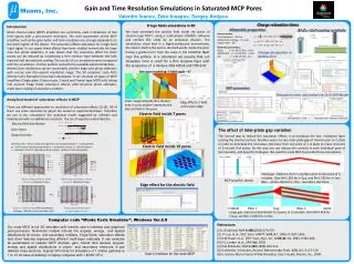
Gain and Time Resolution Simulations in Saturated MCP Pores Valentin Ivanov, Zeke Insepov, Sergey Antipov 1 First Author Institution, 2 Second Author Institution, 3 Third author Institution. Muons, Inc. Introduction

E N D
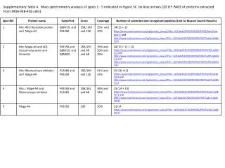
Gain and Time Resolution Simulations in Saturated MCP Pores Valentin Ivanov, Zeke Insepov, Sergey Antipov 1First Author Institution, 2Second Author Institution, 3Third author Institution Muons, Inc. Introduction Micro channel plate (MCP) amplifiers are commonly used in detectors of fast time signals with a pico-second resolution. The main parameters of the MCP amplifier, such as the gain factor and time resolution are strongly dependent on the work regime of the device. The saturation effects take place for a high-level input signal. In our paper these effects have been studied numerically for large area fast photo detectors. It was shown that the saturation effect for short pulses can be reduced by introducing a thin resistive layer between the bulk material and the emissive coating. The results of our simulations were compared with the simulations of other authors and with the available experimental data.. Monte Carlo simulations can be successfully used for large area photo detectors with micron and Pico-second resolution range. The 3D computer code MCS (Monte Carlo Simulator) have been developed. It can simulate all types of MCP amplifiers (Single plate, Chevron pair, Z-stack and Funnel-type MCP) with taking into account fringe fields, saturation effects, pillar-structure photo cathodes, multi-layer coating of secondary emitters. We have simulated the electric field inside the pores of chevron-type MCP’s using a multi-physic COMSOL software and verified this study by an analytical solution. The simulations show that in a highly-conductive environment, the electric field in the pore is directed axially inside the pore, having a gradual turn from the value in the resistive layer near the surface. In a simulation we assume that ε/σ relaxation time is small for a thin resistive layer with the properties of a mixture 30% Al2O3 and 70% ZnO. Charge relaxation times Fringe fields simulations in 3D Materials properties Al2O3 + ZnO coating resistivity Pore structure Pore diameters – 20 mm Al2O3+ZnO coatings – 1-5 mm Aspect ratio -- 40 Materials parameters: Glass: s = 110-17 S/m, e=5.8 Al2O3+ZnO: s = 110-8 S/m, e=6.9 Air: s = 110-17 S/m, e=1 Charge dissipation in Al2O3+ZnO One-pore modeling: E-field angle ~ 8° MCP parameters Relaxation time calculated via Drift-Diff.Model Analytical model of saturation effects in MCP There are different approaches to simulation of saturation effects [1]-[5]. All of them use some constants to adjust the model to experimental data. Therefore we use in our simulations the analytical model suggested by A.Berkin and V.Vasilev [6] with no additional constants. The set of equations describes the Color: Angle=Atan(Ex/Ez). Stream- lines in cross section represent the electric field in the pore. Edge Effects: E-field at the pore edge Electric field inside 7 pores Hole densities vs. time Relaxation time vs diffusion coefficients Electric field distribution The effect of inter-plate gap variation The normal way to reduce the saturation effects is to introduce the low- resistance layer coating the channel surface. Another way is to vary inter-plate gap of chevron pair or Z-stack in order to distribute the secondary electrons from one pore of 1-st plate to many channels of 2-nd and 3-rd plates. By this way one can reduce the currents in each individual pore of last cascades, and keep the total gain. We used the code MCS to provide those simulations. Gain factor Shape function Here Ezo, Mo – electric field and a gain for non saturated mode; T – pulse period; Io – initial current of photo electrons, Ir – resistance current; ts - off-duty factor; τ – relaxation time for induced positive charges, resistive material property. Electric field inside 19 pores Small gap. Electrons from 1-st plate come to one pore of 2-nd plate. Gain M=1.2E6 for τ=1μs, and M=1.5E5 for τ=1ms. Blue – photo electrons; red – secondary electrons. Electric field profile vs. initial current I, relaxation τ=6μs. MCP-current profile vs. initial current I, relaxation τ=6μs. MCP amplifier sketch. Edge effect for the electric field Gain vs. initial current MCP parameters: D=20μm, L/D=40, U=1kV, Gain Mo=1.E6 Time resolution variations vs. the initial current I. Large gap. Electrons distributed to 3 pores of 2-nd plate. Gain M=3.4E6 for τ=1μs, and M=1.13E6 for τ=1ms. Computer code “Monte Carlo Simulator”, Windows Ver.2.0 References [1] L.Giudicotti, NIM A 480(2002) 670-679. [2] P-L.Liu et al., IEEE Trans. MWTT, V.47, N7, 1999.-P.1297-1303. [3] G.W.Fraser et al., IEEE Trans. Nucl. Sci., V.NX-30, N1, 1983.-P.455-460. [4] O.L.Landen et al., SPIE Vol. 2002 [5] P.M.Shikhalev, NIM A 420 (1999) 202-212. [6] A.B.Berkin, V.V.Vasilev, ZhurnalTekhnicheskoiFiziki, V.76, N2.-P.127-129. [6] V. Ivanov, Micro Channel Plate Simulator, User’s Guide, Muons, Inc., 2009. The code MCS is full 3D simulator with friendly user’s interface and graphical post-processor. Numerical models include the angular, energy and spatial distributions for photo- and secondary emitters, fringe fields, saturation effects and other features representing different multi-layer materials. It can evaluate all parameters of realistic MCP devices: gain, transit time spread, angular, energy and spatial distributions of photo- and secondary electrons in pre defined cross-sections. Typical CPU-time for simulation of 1 million particles is 1 to 10 minutes at desktop or laptop computer with 1.8GHz CPU. User’s interface for the code MCP