Download

1 / 20
210 likes | 376 Views
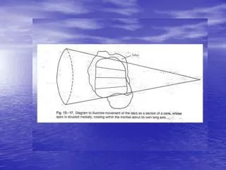
Device for Collecting Stress Images of Subtalar Joint. Final Presentation Patrick Melton Daniel Escobar 4/26/11. Hindfoot Anatomy. Purpose.

E N D
Device for Collecting Stress Images of Subtalar Joint Final Presentation Patrick Melton Daniel Escobar 4/26/11
Purpose • Create a device that will apply stress to the subtalar joint for the best possible radiographic images to allow for accurate measurements and determine the stability of the joint.
Cobey View Reilingh, M., Beimers, L., Tuijthof, G., Stufkens, S., Maas, M., & van Dijk, C. (2010). Measuring hindfoot alignment radiographically: the long axial view is more reliable than the hindfoot alignment view. Skeletal Radiology, 39(11), 1103-1108.
Long Axial Alignment View • Reilingh, M., Beimers, L., Tuijthof, G., Stufkens, S., Maas, M., & van Dijk, C. (2010). Measuring hindfoot alignment radiographically: the long axial view is more reliable than the hindfoot alignment view. Skeletal Radiology, 39(11), 1103-1108.
Final Design • 30 degree plate inclination with additional forefoot plate that rotates 15 degrees. • Sliding heelcup plate for various foot sizes. • Allows for footstraps to be placed in multiple areas.
Final Design • Utilizes two bolts that act as columns to angulate the foot for optimal positioning of the subtalar joint.
Dimensions - Bolts 15° Ø 0.5” UNF – 20 Hex Head bolt Ø 1.125” UNF – 12 Hex Head bolt
Hinge: Ø 0.5” Outer Ø 0.25” Inner Dimensions - Hinges Hinge: Ø 1.0” Outer Ø 0.5” Inner Shoulder screw - Ø ½”, 3/8”–16 thread with matching nut. Shoulder screw – Ø ¼” #10–24 thread with matching nut.
Finite Element Analysis – Foot Plate • Max Displacement: .0618 in.
Finite Element Analysis – Foot Plate • Max Stress: 2550 psi • Safety Factor: 3.92
Finite Element Analysis – Base Plate • Max Displacement: .0362 in.
Finite Element Analysis – Base Plate • Max Stress: 1180 psi • Safety Factor: n = 8.47
Finite Element Analysis – Forefoot Plate • Max Displacement: .0273 in.
Finite Element Analysis – Forefoot Plate • Max Stress: 8970 psi • Safety Factor: n = 1.12
Materials Selection • Most of the device will be made from a radiolucent plastic called Delrin, manufactured by DuPont. • Tensile strength – 400 ksi • Yield Strength – 10 ksi • Density – 1.42 g/cm3 • Footstraps made from Nylon • Foam padding (Lux-R-Foam) on sliding plate, forefoot plate, and in heelcup.