Download
1 / 14
150 likes | 293 Views
1. The Multi-Pinch Experiment as first step towards PROTO-SPHERA. Paolo Micozzi , Franco Alladio , Alessandro Mancuso, 1 Stamos Papastergiou and 2 François Rogier CR-ENEA, CP 65, 00044 Frascati (Roma), Italy 1 Euratom-Enea , 2 ONERA Toulouse, France. Outline PROTO-SPHERA purpose & aims

E N D
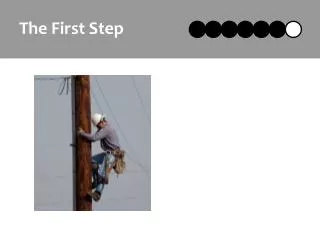
1 The Multi-Pinch Experiment as first step towards PROTO-SPHERA Paolo Micozzi, Franco Alladio,Alessandro Mancuso,1Stamos Papastergiou and 2François Rogier CR-ENEA, CP 65, 00044 Frascati (Roma), Italy1Euratom-Enea ,2ONERA Toulouse, France • Outline • PROTO-SPHERA purpose & aims • Theoretical basis & analysis • Multi-Pinch: the first phase of PROTO-SPHERA • Conclusions
2 PROTO-SPHERA Aimsat producing a spherical torus (ST) with a screw pinch (SP) replacing the centerpost Ie, Ip = 40, 50 kA pinch, ST currentsIe, Ip = 60, 240 kAA = 1.6 aspect ratioA ≤ 1.3tpulse = 80 ms~110 tApulse durationtpulse ≥ 70 ms~1 tR Goals: sustain the plasma (Helicity Injection SPST) for more than tR=m0a2/h (resistive time)and compare tE with START
3 PROTO-SPHERA & Spheromaks (TS-3) Two important requirements are different for the PROTO-SPHERA equilibria with respect to Flux-Core-Spheromaks like TS-3: 1)Tokamak-like safety factor profile of ST: q0~0.94, q95~2.6 at the edge 2) Strong jump of the surface averaged relaxation parameter <>=0<j•B/B2> between SP and ST Helicity Injection (~35 m-1 inside SP, ~10 m-1 inside ST) PROTO-SPHERA (Rsph=0.35 m) has been designed in order to be as far as possible from the pure Spheromak STRsph≤4.49 eigenvalue
4 Physics & Engineering Design ST diameter = 0.7 mToroidal plasma current Ip= 240 kA Aspect ratio A = 1.2Elongation k = 2.35 Pinch current Ie= 60 kA Engineering design complete (geometry, stresses and temperatures)
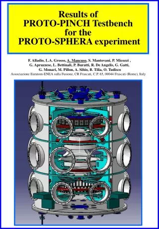
5 Main Breakdown features Proto-Pinch Testbench (Ie~ 700 A) Screw Pinch (SP) formed by a hot cathode breakdown • Filling pressure pH~10-3÷10-2 mbar • Cathode filaments (W) heated to 2600 °C • Ve~100 V applied on the anode • Electrode arc current limited to Ie~8.5 kA
6 Theoretical analysis of the PROTO-SPHERA configuration Equilibria: •formation phase fully analyzed • equilibrium resilience checked by varing the functional forms of p(y) & f(y) both on the SP and on the ST All equilibria has been obtained with the same coils set Stability: • New free boundary ideal MHD code developed plasmas extending up to the symmetry axis (R=0) with regular (|B|≠0) & singular (|B|=0) X-points Investigation about the resistive MHD instabilities, evaluation of the Helicity Injection efficency both from a macroscopic as well as a microscopic point of view are in progress
7 n=1 PROTO-SPHERA Stability Results • n=1,2,3 investigated for all equilibria • Main constraintIST/Ie • Stability obtained for: • b =21÷26% , IST/Ie= 0.5 - 1 • b= 14÷15% , IST/Ie= 2-4 • With bT0=2m0<p>vol/< >vol • bT0=28÷29% , IST/Ie= 0.5 - 1 • bT0=72÷84% , IST/Ie= 2-4 • The dominant instabilities are: • up to IST/Ie≈3 Spherical Torus • instabilities • IST/Ie> 3 Screw Pinch kink instabilities IST/Ie = 5 and b»15% Unstable
8 Multi-Pinch Experiment Aims: Stable Screw Pinch plasma with the full dimension and disk shape, but reduced current Ie (2.7 Vs. 8.5 kA) Philosophy: Almost all parts should be reutilized in PROTO-SPHERA START vacuum vessel (In Frascati since May 2004) • Simplified PF coils system with constant current: • under construction in Ansaldo (Genova, Italy), • fully recoverable for PROTO-SPHERA • Fed with 0.6 kA, 120 V (no water cooling) • (1.9 kA, 350 V in PROTO-SPHERA)
9 START in Frascati Arrival May 2004 Disassembling October 2004
10 Multi-Pinch Experiment (first phase) Cathode plasma only is disk-shaped Power density on the “single” anode ~ PROTO-SPHERA
11 Multi-Pinch Experiment (second phase) Anode & Cathode plasma disk-shaped Definitive PROTO-SPHERA Anode Possibility of arc anchoring needs of saddle coils?
12 Multi-Pinch Cathode Definitive PROTO-SPHERA Cathode, but only partially filled
13 Wire Length = 400 mm Conical terminal & clamp Multi-Pinch Cathode W wires • Multi-Pinch test is proposed with a limited number of cathode modules • (18 Vs. 378) • Wires will drive a limited total current (2.7 kA Vs. 60 kA) inside the pinch, simplifying the power supply for Multi-Pinch • Each wire will be capable of delivering the design current (150 A) Mo support
14 Conclusions • PROTO-SPHERA aims to explore the feasibility of a ST formed • around a SP, with respect to the possibility to sustain it through • Helicity Injection on resistive time scale • An exhaustive range of PROTO-SPHERA scenarios has been • investigated (resilience of the equilibria Vs. internal profile & • ideal MHD stability boundaries) • The Multi-Pinch experiment will investigate the feasibility of a • stable mushroom-shaped Screw Pinch • Multi-Pinch will be built inside theSTARTvacuum vessel, • PROTO-SPHERA can be obtained with a modular • implementation of this experiment