Download
1 / 26
260 likes | 273 Views
This talk outlines the engineering design and analysis of PROTO-SPHERA, a screw pinch experiment. The design philosophy, aims, and operating conditions are discussed, along with the thermal and heat transfer behavior, electromagnetic forces and stresses, and the multi-pinch experiment. The timetable for the project is also presented.

E N D
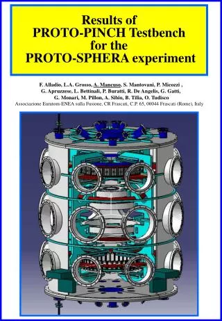
Status of the Multi-Pinch/Proto-Sphera Load Assembly Stamos Papastergiou, Franco Alladio, Alessandro Mancuso, Paolo MicozziCR-ENEA, CP 65, 00044 Frascati (Roma), Italy Outline of the Talk • Introduction to PROTO-SPHERA • Engineering Design and Analysis of PROTO-SPHERA • Multi-Pinch Experiment • Timetable • Conclusions
Main Breakdown features • Screw pinch (SP) formed by a hot cathode breakdown • Filling pressure pH~10-3÷10-2 mbar • Cathode filaments heated to 2600 °C • Ve~100 V applied on the anode • Initial electrode arc current limited to Ie~8.5 kA
Design Philosophy • Simplicity, symmetry, conservatism. • Viewing capability and good access to electrodes. • All connections to PF coils from top and bottom flanges, external to Machine. • Bellows in coil feedthroughts for adjustment. • Operation and disruption (but no fault) conditions considered.
Design Aims • Operationability, Reliability, Repairability of Machine. • Reliability of electrodes and avoidance of arc anchoring. • Minimise Technological Risks: provide appropriate elecrical insulation, avoid local coil overheating ( >100°C ) due to hot anode and cathode ( 12MJ, 2750°C ) • minimise electromagnetic stresses.
Operating conditions Temperature 20°C Vacuum < 1•10-7 mbar (predicted outgassing rate: ~3•10-5 mbar•l/s) Baking 80-90°C Adequate for water removal, coil protection; compatible to Viton O-rings Possibility of N2 1 mbar contact gas
Machine Parameters Spherical Torus (ST) diameter 0.7 m Longitudinal Screw Pinch current 60 kA Toroidal ST current 120÷240 kA Plasma pulse duration 1 s Minimum time between two pulses 5 min. Maximum heat loads on first wall componenets in divertor region 2 MW/m2 , for 1 ms Maximum current density on the plasma-electrode interface 1 MA/m2
Protection Componenets Thermal and Heat Transfer Behaviour Philosophy: collect the heat ( via radiation ) from the electrodes to black resilient componenet and then conduct or radiate it away in a controlled way. Hot spots are thus avoided. Danger: the hot cathode (less the anode) radiates at 2750°C with ~3.5MW/m2 and even a 10mm thick coil casing cannot sustain this power density for more than 0.5s without exceeding 100°C
Thermal and Heat transfer Behaviour Solution: • Use of Cu componenets to collect or reflect the heat away from coils. Conservative (but symmetrical) design for the anode. Thermal mass of these components results in operational temperature < 100°C. Water cooled! Optimum design; i.e. one circuit/component, D~10-15mm, v~2m/s, duty cycle 5min. • Use of thermocouples in no water cooled componenets to avoid >100°C with frequent pulses; every 5min. • Use of 10mm divertor AISI 304LN plates. 2 MW/m2 for 1 s gives DT~120°C, sth~320MPa • Use of optical diagnostics to view the electrodes which are relatively easily accessible.
Electromagnetic Forces and Stresses B=50T/s B=500G t≤1 ms Subdivision of Cu and 304LN plates to achieve ≤100 MPa of eddy current stresses. Unaccounted skin effects (t ~1ms) significant. Conservative prediction of eddy current effects. Electromagnetic forces in the coils (~x10 weight) require to be sustained.
Predicted and Permitted Stresses ASME III-NB 3221 Stainles Steel Allowable Sm for 304LN 100°C : 200MPa [304L Sm~150MPa] Predicted e-m stresses : 320MPa Thermal (divertor) local stresses : 320 MPa (2 MW/m2 ,1s) Criterion 1 : 100 <200x1.5 Criterion 2 : 100320 <200x3 Copper Minimum required allowable at 100°C> 70 MPa (100MPa<70x1.5) Thus sy >115 Mpa and su > 230 MPa at 20°C i.e. Cu hardenned
Multi-Pinch Experiment Multi-Pinch Experiment Provisional single anode Cathode START Vacuum Vessel Aim: verification of the arc formation & stability ~ START DimensionPinch Current Ie=8.5 kA(same of ProtoSphera) - PF-Coils do not need cooling
START in Frascati Arrival May 2004 Disassembling October 2004
ELECTRICAL CONDUCTORS Cu GAS W80%Cu ≤1000°C ANODE PHASE - ASSEMBLY
ELECTRICAL CONDUCTORS Cu WCu WATER ANODE PHASE 2 - ASSEMBLY GAS
ELECTRICAL CONDUCTORS GAS WCu WATER COOLED PROTECTION PLATES SECTION OF ANODE PHASE 2
Protection Plate Cu W-Cu SECTION OF ANODE PHASE 2 SECTOR
ELECTRICAL CONDUCTORS Water W Cu CATHODE - ASSEMBLY
CATHODE - CROSS SECTION WATER COOLED PROTECTION PLATES W Cu 15 V Mo
MultiPinch Coils Delivery: 04/06/2007 EURATOM, ENEA & ASG Personnell
MultiPinch Timetable • Delivery of Load Assembly *September 2009 • I.a Construction & Delivery Magnetic Diagnostics to ASG * April 2009 • II International Tender Action for Construction • of Power Supplies * March 2009 • II.a Delivery of Power Supplies * June 2010 • III Site Preparation *June 2009 • IV Services (Vacuum, Electricity, Diagnostics)*June 2010 • V Commissioning* December 2010 • VI First Plasma* December 2010
CONCLUSIONS • There is high degree of confidence that the design, construction and reliable operation of PROTO-SPHERA are feasible • The Multi-Pinch experiment is being constructed to prove the formation and stability of the PROTO-SPHERA initial arc • The PF Coils have been delivered, while the Load Assembly is half way in construction using the START Vacuum Vessel • First Plasma can be obtained in December 2010 • PROTO-SPHERA can be obtained by simply adding components to Multi-Pinch