Download
1 / 34
340 likes | 470 Views
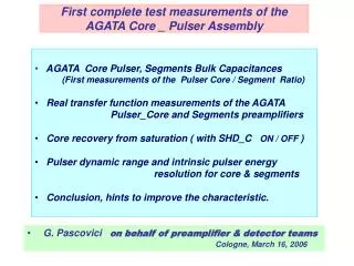
First complete test measurements of the AGATA Core _ Pulser Assembly. AGATA Core Pulser, Segments Bulk Capacitances (First measurements of the Pulser Core / Segment Ratio) Real transfer function measurements of the AGATA

E N D
First complete test measurements of the AGATA Core _ Pulser Assembly • AGATA Core Pulser, Segments Bulk Capacitances • (First measurements of the Pulser Core / Segment Ratio) • Real transfer function measurements of the AGATA • Pulser_Core and Segments preamplifiers • Core recovery from saturation ( with SHD_C ON / OFF ) • Pulser dynamic range and intrinsic pulser energy • resolution for core & segments • Conclusion, hints to improve the characteristic. . • G. Pascovici on behalf of preamplifier & detector teams • Cologne, March 16, 2006
One-wire test pulse for all segments A.Pullia, presented at AGATA week, GSI, Feb.2005 also: “Test of a new low-noise preamplifier with the MARS segmented detector and extraction of physical data from the noise measurements” presented at EDAQ meeting, Padova, Sept. 19-20, 2002 From an idea available in literature
Pulser • PTFE Coaxial Cable (0.9mm) Pulser Resolution in Core( < 1.5 keV @ tr ~ 30-35 ns ) Advantage - Disadvantage * Pulser return ground signal 0 to 40 mA Rectangular - Signal & Pulser same P/Z adj. - DC level Exponential • good DC level • at low count. rates Signal & Pulser different P/Z
Pulser block diagram Rectangular or Exponential form Attenuation 0 to 40 dB
Triple Cryostat Wirering_Grounding - GND_0Cold part - GND_1 Warm Part Ro [GND0 <-> GND1] LN2 - DEWAR Al Al D1 D2 D3 CB CB GND0 • Pulser @ GND_1 (!) • Core & Segments @GND_0 GND_1 CD CC CS CF CF CF CS RF RF RF VACUUM Problems: • twisted Core Signal_GND? - Segments return GND ?! - GND one_both ends ?! • thermal shunt limitations • pulser wirering, return GND (very important up to 40 mA !) • Connector problems: - only MicroMatch(20)? - formerly also MDR-26? • we badly need a test Cryostat ! ( HP-Ge Detector thermal stress) GND_0 cold part 1.8Ω ~12-15cm ~12-15cm CTT Feed through x36 x3 ~8cm x36 ~8cm MicroMatch (20) MicroMatch (20) MicroMatch (20) GND_1 6x TRIPLE CORE + PULSER 6x TRIPLE SEGMENTS SEGMENTS MicroMatch (18) MicroMatch (18) MicroMatch (18) ~8cm ~8cm PTFE ~8cm MDR(26) GND_1 MDR(26) GND_1 MDR(26) GND_1
Cluster of three detector – • and the related GND_ing problem • Common Core_GND (cold_warm?) • Individual GND_0 (cold) • Resistance between GND_0 GND_1 • Superposition of individual , • time dependent, • Core_Return_GND_Signals • Strong crosstalk due to BLR effect • if the R( GND_0 GND_1)
Very Fast Pulser(TEK type PG-502; tr ~ 1ns) • Pulser rise time • tr~ 1ns / 50 Ohm • Core / Segment fastest • transfer function • Overshoots ~ 20-40 % • (but adjusted on bench • for NO overshoot !)
FAST PULSER( tr ~ 10, 50 ns ) core core segment segment Pulser tr ~ 50 ns Pulser tr ~ 10 ns • tr segments ~ 25 ns @ ~15-20 pF • trcore ~ 29 ns @ ~ 45 pF • we haveto understand the equivalent • “transfer function” of the pulser signals • for core and segments ! • Both core and segments preamplifiers • bench adjusted for fastest transfer • function with no ringing for pulser signals • with tr > 10 ns and/or for core_pulser • tr > 65 ns
High Precision Slow PulserPulser PB-4 ( tr ~ 100; 250 ns) Triple with Det. & twisted core. Triple with Det. & twisted core core core segment segment Pulser tr ~ 100 ns Pulser tr ~ 250 ns Pulser tr ~ 100 ns No twisted core No twisted core core core segment segment Pulser tr ~ 100 ns Pulser tr ~ 250 ns Pulser tr ~ 100 ns
Pulser Core /Segments Ratio Uncorrected for individualGain R ~ (40-75) Gain corrected
Distribution of the real Segment Preamplifiers Gain (cold + warm) • N.B. a) but with a distribution of the warm preamplifier gain of < +/- 2 % ! b) to reduce the influence of feedback capacitor a new design of cold part is mandatory ( … silica substrate could be a very good candidate but it’ll bring additional technological problems !)
Recovery from core saturation versus SHDW command • Recovery time in • < 2 us after INH. • Saturation @ ~ • 100MeV (equivalent • gamma) SHD_COFF SHD_C ON • Maximum “Dead Time” • SHD_C OFF ~ 45 µs • SHD_C ON ~ 12.8 µs SHD_C ON SHD_C ON
Amplitude to Time Converter Core “Saturated “ Pulses • Active Reset _”Saturated “ Core • ‘Amplitude to Time Converter’ • for saturated core pulses and • Non saturated Segment pulses
Core_Pulser Programmable Attenuation • Coarse Attenuation • in four steps of 10 dB • (0; 10; 20; 30; 40 ) Attn 40 dB Attn 20 dB
Linear Amplitude to Time conversion of the “saturated” reset pulses • “VIP“ signals • (~ 12 – 25 MeV) • linearity < 2% • resolution < 1%* * see also A.Pullia, F.Zocca
“Saturated” Pulses Linear Amplitude-Time converter • “VIP“ signals • (~ 30 – 100 MeV) • linearity < 2% • resolution < 1% • F. Zocca, A new low-noise preamplifier for • gamma ray sensors with smart device • for large signal management. • Laurea Degree Thesis, Univ. of Milan, 2004
Core baseline deterioration at very large signals Core baseline deterioration at very large signals versus pulser mode of operation: a)exponential ( decay time 100µs) • a(1)@ ~ 15 MeV; • a(2)@ ~90 MeV b)rectangular @ ~ 90 MeV a(1) a(2) b)
Core Rise Time versus I(D), C(v) Core Rise Time / I(Drain) Core Rise Time / C(v) (*) Rise Time [ns] Rise Time [ns] C(v) [pF] I (Drain) [mA] (*) Pulser PB-4 (BNC) @ 50ns rise time
Fast core rise time range • Core_Pulser constant tr~30ns • Corerise time rangetr: 30-60 ns Segment Ringing versus Core Bandwidth (a) tr ~ 32 ns tr ~ 38 ns tr ~ 46 ns tr ~ 60.5 ns
Slow core rise time range • PB4_Pulser (tr~ 50 ns) • Core rise time tr: 60-100 ns Segment Ringing versus Core Bandwidth (b) tr ~ 62 ns tr ~ 72 ns Tr~ 32ns tr ~ 98 ns tr ~ 76.5 ns
Segment Overshoot versus Core Rise Time • Unexpected dependence • between core rise time • (not only pulser rise time) • and segments overshoot • (to understand that see also • cableling details on pag. 5–7 • i.e. core return ground signal)
Rise Time versus Amplitude LM6171 • LM 6171 data sheets ( +/- 12V ) • tr~ 28 ns @ 50 mV 24 ns @ 1000 mV (terminated @ R=100 Ohm) Alternatives : • AD8057(Volt.Feedback) ( +/- 6V only ) < 1.5 ns • LMH6723 (CurrentFeedback) ( +/- 6V only ) < 1.5 ns ( I quiescent ~ 3 mA ) AD8057 ( I quiescent ~ 6 mA )
Intrinsic Pulser Resolution ( < 1keV @ tr ~30 ns ) 122 keV 57 Co Pulser • Intrinsic Core_Pulser • resolution measured • at different segments • < 900 eV ! • Equivalent energy range • in segments: • ~ 10 keV- 3 MeV ! X- Pb 136 keV
Intrinsec Pulser Resolution ( < 1keV @ tr ~30 ns ) 57 Co Pulser (Rectangular) (equiv. ~3.3MeV) • Highest Pulser • Amplitude in segments • ~ 3.3 MeV (equivalent • gamma) • ( in Core saturated @ • ~100 MeV respectively) 60 Co
122 keV Pulser (-) 136 keV X_Pb Pulser Resolution in Core ( < 1.5 keV @ tr ~30 ns ) • Intrinsic Core resolution in • AGATA Triple Cryostat (01) • with NO Pulser 1.3 keV • with Pulser ON 1.5 keV 122 keV 1173 keV 1173 keV Pulser (+) 1332keV Pulser (-) 1332keV Pulser (+) • Pulser Mode • Pulser Exponential • Pulseform • (decay time 100µs) • (+) normal • (-) supressed 20:1 136 keV X_Pb
Structure of Core Resolutionin Coincidence with Segments Rings Nigel Warr, “AGATA core resolution with gate on segment
Cryostat Wirering_Cableling • Segments: - two detectors self made “flat band” cable, one individual Cu(Be) wires - one GND_0 / detector, no twisted cable • Core: - twisted cable for D and FB signals at GND_0 (in the case of only one detector), - if all three detectors at common GND then large crosstalk (due to the superposition of Return_GND(i) signals) - Corereturn GND on the segments cold motherboard! • Pulser: - Pulser coaxial PTFE, 0.9 mm external diameter with individual GND_1 • Warm Core_CSP: - common GND for Pulser & CSP > most probable has to be changed ?! - on board separation between A_GND and D_GND, but only one GND to the F_ADCs (as decided by Infrastructure Group, Feb. 2005) - differential outputs, with the same polarity as Segments, as well as the INH_C and SHD_C signals functionality identical to the INH_A(B) and SHD_A(B), respectively. • Triple CryostatWirering: - has to be decided, as soon as possible !
Conclusions • Test demonstrated that a pulser with a very good energy resolution (< 1keV @ segments , < 1.5keV @ core) with a rather good very long time stability and fast rise time (< 35 ns) can be obtained, • Further developments of core_pulser assembly is mandatory (to reduce the core CSP noise with pulser , to optimize pulser rise time if “in situ” transfer function measurements are foreseen), • Solution to improve the wirering in the triple cryostat have been presented by A.Pullia at the AGATA week, Strasbourg, Nov. 2005 (next two slides), (milestones for the above mentioned tasks has to be decided)
Position of cold preamps for nearest neighbours event D. Weisshaar et al. AGATA Week, GSI, Feb. 2005
Crosstalk Core versus Segment Open Loop Gain B. Bruyneel – PhD Thesis , IKP-Cologne, 2006
Crosstalk Segments versus Core_Open Loop Gain B. Bruyneel – PhD Thesis , IKP-Cologne, 2006