Stave core assembly
Stave core assembly. Stephanie Yang WP4 face to face meeting, Lancaster University 20 Feb 2014. Outline. Recent Stave building experience Plank#9 –> for wire bonding trial ( to evaluate if C-channel close out is adequate ) Stave building steps Stave tooling Observations. Main Steps.


Stave core assembly
E N D
Presentation Transcript
Stave core assembly Stephanie Yang WP4 face to face meeting, Lancaster University 20 Feb 2014
Outline • Recent Stave building experience • Plank#9 –> for wire bonding trial (to evaluate if C-channel close out is adequate) • Stave building steps • Stave tooling • Observations
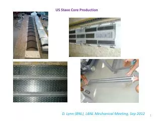
Main Steps • (Tape + CF prepreg) to make a pair of co-cured face sheets • Glue lower foam blocks • Glue cooling pipe, upper foam blocks and end closeouts • Glue CF c-channels (side closeouts) • Glue honeycomb core • CNC machine to the designated height • Glue the top skin on • Trim Stave to size (using vacuum jig and C channel clamping pieces).
Some pictures Ripped off HC after machining • Partial stave core assembly after CNC machined to the designated core height (4.6mm from the face sheet). • Honeycomb at various places have been ripped off –> not enough glue! • Smaller honeycomb pieces shows better gluing result than the bigger / longer pieces -> possible explanation and it needs to investigate further. • The ripped off honeycomb area have been repaired with Hysoland abrasive paper is used to bring it to the same height as the rest.
Stave tooling • Current stave tooling used: • CF Vacuum Jig • C channel clamping jig • Cooling pipe gluing jig • Rulers and various location blocks • New stave tooling • This includes new vacuum jig; • Stave side close out placement jig; • Other new jigs / modification on existing jig design as required.
New Vacuum jig • Various hole patterns need to be added on the vacuum jig for the stave tooling (e.g. holes for reference corner pieces, c channel clamp jig, etc….). In addition, it • Provides reference features for gluing the locking points. • Provides 2 off 10mm dia dowel through holes and 8 off M10 clearance through holes are needed for positioning and fixing the vacuum jig onto the sub-plate of the CNC machine at Oxford (steel insertspreferred, holes go through those Steel pads at the bottom side of the jig). See next slide for detail. • Max length of the jig has to be under 1.6m. 8 off M10 clearance hole thru 2 off 10mm dia Dowel hole thru
X-section view Steel bush built into the vacuum jig Vacuum jig that holds the stave core Steel pad Sub-plate on CNC machine
Stave side closeout placement jig • C channel clamping jig new design allows the variable stave width. • If the stave side closeouts is changed from CF C-channels into other shaped channels (e.g. box section), this design will have to change.
Observations • The old procedure suggested that the lower foam blocks glued on the face sheet first, then machine the cooling pipe channels and also to height; but recently 2 or 3 staves were done by machining the lower foam blocks to size before gluing to the face sheet. Need to decide which way to go. • The cooling pipe gluing jig worked well, but need to improve (e.g. current jig can’t go through U-bend, also is difficult to hold it during the applying of the glue process). New jig should address these areas. • Honeycomb core gluing - we should cut the honeycomb into smaller pieces and see if this gives better gluing quality. • Need to design a proper glue bath for gluing the top skin. (Features like a Al plate with 0.5mm depth recess, and some reference features for Stave core partial assembly, and some indicators show where the cooling pipe locates etc) • The way we did for trimming stave to size worked all right. • All the tooling (e.g locations blocks and C channel clamping pieces, etc) need to be clearly marked, for correct position on jig.