CHAPTER 20 Temperature Sensors
CHAPTER 20 Temperature Sensors. OBJECTIVES. After studying Chapter 20, the reader will be able to: Prepare for ASE Engine Performance (A8) certification test content area “E” (Computerized Engine Controls Diagnosis and Repair).

CHAPTER 20 Temperature Sensors
E N D
Presentation Transcript
CHAPTER 20 Temperature Sensors
OBJECTIVES After studying Chapter 20, the reader will be able to: • Prepare for ASE Engine Performance (A8) certification test content area “E” (Computerized Engine Controls Diagnosis and Repair). • Explain the purpose and function of the ECT and IAT temperature sensors. • Describe how to test temperature sensors. • Discuss how automatic fluid temperature sensor valves can affect transmission operation.
Cylinder head temperature (CHT) Engine coolant temperature (ECT) Engine fuel temperature (EFT) Negative temperature coefficient (NTC) Throttle-body temperature (TBT) Transmission fluid temperature (TFT) KEY TERMS
ENGINE COOLANT TEMPERATURE SENSORSPURPOSE AND FUNCTION • Computer-equipped vehicles use an engine coolant temperature (ECT) sensor. • When the engine is cold, the fuel mixture must be richer to prevent stalling and engine stumble. • When the engine is warm, the fuel mixture can be leaner to provide maximum fuel economy with the lowest possible exhaust emissions. • Because the computer controls spark timing and fuel mixture, it will need to know the engine temperature. • An engine coolant temperature sensor (ECT) screwed into the engine coolant passage will provide the computer with this information.
FIGURE 20–1 A typical engine coolant temperature (ECT) sensor. ECT sensors are located near the thermostat housing on most engines. ENGINE COOLANT TEMPERATURE SENSORSPURPOSE AND FUNCTION
ENGINE COOLANT TEMPERATURE SENSORSPURPOSE AND FUNCTION • The ECT sensor is also used as an important input for the following: • Idle air control (IAC) position • Oxygen sensor closed-loop status • Canister purge on/off times • Idle speed
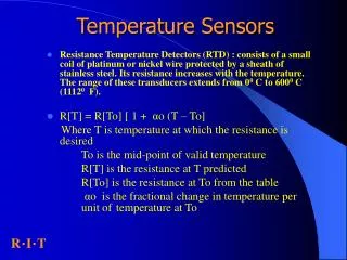
ENGINE COOLANT TEMPERATURE SENSORSECT SENSOR CONSTRUCTION • Engine coolant temperature sensors are constructed of a semiconductor material that decreases in resistance as the temperature of the sensor increases. • Coolant sensors have very high resistance when the coolant is cold and low resistance when the coolant is hot. • This is referred to as having a negative temperature coefficient (NTC), which is opposite to the situation with most other electrical components.
FIGURE 20–2 A typical ECT sensor temperature versus voltage curve. ENGINE COOLANT TEMPERATURE SENSORSECT SENSOR CONSTRUCTION
ENGINE COOLANT TEMPERATURE SENSORSSTEPPED ECT CIRCUITS • Some vehicle manufacturers use a step-up resistor to effectively broaden the range of the ECT sensor. • Chrysler and General Motors vehicles use the same sensor as a non-stepped ECT circuit, but instead apply the sensor voltage through two different resistors. • When the temperature is cold, usually below 120°F (50°C), the ECT sensor voltage is applied through a highvalue resistor inside the PCM. • When the temperature is warm, usually above 120°F (50°C), the ECT sensor voltage is applied through a much lower resistance value inside the PCM.
FIGURE 20–3 A typical two-step ECT circuit showing that when the coolant temperature is low, the PCM applies a 5-volt reference voltage to the ECT sensor through a higher resistance compared to when the temperature is higher. ENGINE COOLANT TEMPERATURE SENSORSSTEPPED ECT CIRCUITS
FIGURE 20–4 The transition between steps usually occurs at a temperature that would not interfere with cold engine starts or the cooling fan operation. In this example, the transition occurs when the sensor voltage is about 1 volt and rises to about 3.6 volts. ENGINE COOLANT TEMPERATURE SENSORSSTEPPED ECT CIRCUITS
TESTING THE ENGINE COOLANT TEMPERATURE SENSOR • TESTING THE ENGINE COOLANT TEMPERATURE BY VISUAL INSPECTION • The correct functioning of the engine coolant temperature (ECT) sensor depends on the following items that should be checked or inspected: • Properly filled cooling system. • Proper pressure maintained by the radiator cap • Proper antifreeze–water mixture • Proper operation of the cooling fan
FIGURE 20–5 Measuring the resistance of the ECT sensor. The resistance measurement can then be compared with specifications. (Courtesy of Fluke Corporation) TESTING THE ENGINE COOLANT TEMPERATURE SENSOR • TESTING THE ECT USING A MULTIMETER • Both the resistance (in ohms) and the voltage drop across the sensor can be measured and compared with specifications.
FIGURE 20–6 When the voltage drop reaches approximately 1.20 volts, the PCM turns on a transistor. The transistor connects a 1-kΩ resistor in parallel with the 10-kΩ resistor. Total circuit resistance now drops to around 909 ohms. This function allows the PCM to have full binary control at cold temperatures up to approximately 122°F, and a second full binary control at temperatures greater than 122°F. TESTING THE ENGINE COOLANT TEMPERATURE SENSOR
FIGURE 20–7 An ECT sensor being tested using a digital meter set to DC volts. A chart showing the voltage decrease of the ECT sensor as the temperature increases from a cold start. The bumps at the bottom of the waveform represent temperature decreases when the thermostat opens and is controlling coolant temperature. TESTING THE ENGINE COOLANT TEMPERATURE SENSOR
TESTING THE ENGINE COOLANT TEMPERATURE SENSOR • TESTING THE ECT SENSOR USING A SCAN TOOL • Follow the scan tool manufacturer’s instructions and connect a scan tool to the data link connector (DLC) of the vehicle. • Comparing the temperature of the engine coolant as displayed on a scan tool with the actual temperature of the engine is an excellent method to test an engine coolant temperature sensor. • 1. Record the scan tool temperature of the coolant (ECT). • 2. Measure the actual temperature of the coolant using an infrared pyrometer or contact-type temperature probe.
Quick and Easy ECT Test • To check that the wiring and the computer are functioning, regarding the ECT sensor, connect a scan tool and look at the ECT temperature display. • STEP 1 Unplug the connector from the ECT sensor. The temperature displayed on the scan tool should read about 40. • STEP 2 With the connector still removed from the ECT sensor, use a fused jumper lead and connect the two terminals of the connector together. The scan tool should display about 285°F (140°C). This same test procedure will work for the IAT and most other temperature sensors.
INTAKE AIR TEMPERATURE SENSORPURPOSE AND FUNCTION • The intake air temperature (IAT) sensor is a negative temperature coefficient (NTC) thermistor that decreases in resistance as the temperature of the sensor increases. • The IAT sensor can be located in one of the following locations: • In the air cleaner housing • In the air duct between the air filter and the throttle body • Built into the mass air flow (MAF) or airflow sensor • Screwed into the intake manifold where it senses the temperature of the air entering the cylinders
FIGURE 20–8 The IAT sensor on this General Motors 3800 V-6 engine is in the air passage duct between the air cleaner housing and the throttle body. INTAKE AIR TEMPERATURE SENSORPURPOSE AND FUNCTION
Poor Fuel Economy? Black Exhaust Smoke? Look at the IAT • If the intake air temperature sensor is defective, it may be signaling the computer that the intake air temperature is extremely cold when in fact it is warm. In such a case the computer will supply a mixture that is much richer than normal. • If a sensor is physically damaged or electrically open, the computer will often set a diagnostic trouble code (DTC). This DTC is based on the fact that the sensor temperature did not change for a certain amount of time, usually about 8 minutes. If, however, the wiring or the sensor itself has excessive resistance, a DTC will not be set and the result will be lower-than-normal fuel economy, and in serious cases, black exhaust smoke from the tailpipe during acceleration.
TESTING THE INTAKE AIR TEMPERATURE SENSOR • If the intake air temperature sensor circuit is damaged or faulty, a diagnostic trouble code (DTC) is set and the malfunction indicator lamp (MIL) may or may not turn on depending on the condition and the type and model of the vehicle. • To diagnose the IAT sensor follow these steps: • STEP 1 After the vehicle has been allowed to cool for several hours, use a scan tool, observe the IAT, and compare it to the engine coolant temperature (ECT). The two temperatures should be within 5°F of each other. • STEP 2 Perform a thorough visual inspection of the sensor and the wiring. If the IAT is screwed into the intake manifold, remove the sensor and check for damage. • STEP 3 Check the voltage and compare to the following chart.
TRANSMISSION FLUID TEMPERATURE SENSOR • The transmission fluid temperature (TFT), also called transmission oil temperature (TOT), sensor is an important sensor for the proper operation of the automatic transmission. • A TFT sensor is a negative temperature coefficient (NTC) thermistor that decreases in resistance as the temperature of the sensor increases.
What Exactly Is an NTC Sensor? • A negative temperature coefficient (NTC) thermistor is a semiconductor whose resistance decreases as the temperature increases. In other words, the sensor becomes more electrically conductive as the temperature increases. Therefore, when a voltage is applied, typically 5 volts, the signal voltage is high when the sensor is cold because the sensor has a high resistance and little current flows through to ground. • However, when the temperature increases, the sensor becomes more electrically conductive and takes more of the 5 volts to ground, resulting in a lower signal voltage as the sensor warms.
FIGURE 20–9 A typical temperature sensor circuit. What Exactly Is an NTC Sensor?
ENGINE FUEL TEMPERATURE (EFT) SENSOR • Some vehicles, such as many Ford vehicles that are equipped with an electronic returnless type of fuel injection, use an engine fuel temperature (EFT) sensor to give the PCM information regarding the temperature and, therefore, the density of the fuel.
EXHAUST GAS RECIRCULATION (EGR) TEMPERATURE SENSOR • Some engines, such as Toyota, are equipped with exhaust gas recirculation (EGR) temperature sensors. EGR is a well-established method for reduction of NOX emissions in internal combustion engines. • The exhaust gas contains unburned hydrocarbons, which are recirculated in the combustion process. • Recirculation is controlled by valves, which operate as a function of exhaust gas speed, load, and temperature. • The gas reaches a temperature of about 850°F (450°C) for which a special heavy-duty glassencapsulated NTC sensor is available.
ENGINE OIL TEMPERATURE SENSOR • Engine oil temperature sensors are used on many General Motors vehicles and are used as an input to the oil life monitoring system. • The computer program inside the PCM calculates engine oil life based on run time, engine RPM, and oil temperature.
SUMMARY • The ECT sensor is a high-authority sensor at engine startup and is used for closed-loop control, as well as idle speed. • All temperature sensors decrease in resistance as the temperature increases. This is called negative temperature coefficient (NTC). • The ECT and IAT sensors can be tested visually, as well as by using a digital multimeter or a scan tool. • Some vehicle manufacturers use a stepped ECT circuit inside the PCM to broaden the accuracy of the sensor. • Other temperature sensors include transmission fluid temperature (TFT), engine fuel temperature (EFT), exhaust gas recirculation (EGR) temperature, and engine oil temperature.
REVIEW QUESTIONS • How does a typical NTC temperature sensor work? • What is the difference between a stepped and a nonstepped ECT circuit? • What temperature should be displayed on a scan tool if the ECT sensor is unplugged with the key on, engine off? • What are the three ways that temperature sensors can be tested? • If the transmission fluid temperature (TFT) sensor were to fail open (as if it were unplugged), what would the PCM do to the transmission shifting points?
CHAPTER QUIZ 1. The sensor that most determines fuel delivery when a fuel-injected engine is first started is the ________. • O2S • ECT sensor • Engine MAP sensor • IAT sensor
CHAPTER QUIZ 2. What happens to the voltage measured at the ECT sensor when the thermostat opens? • Increases slightly • Increases about 1 volt • Decreases slightly • Decreases about 1 volt
CHAPTER QUIZ 3. Two technicians are discussing a stepped ECT circuit. Technician A says that the sensor used for a stepped circuit is different than one used in a non-stepped circuit. Technician B says that a stepped ECT circuit uses different internal resistance inside the PCM. Which technician is correct? • Technician A only • Technician B only • Both Technicians A and B • Neither Technician A nor B
CHAPTER QUIZ 4. When testing an ECT sensor on a vehicle, a digital multimeter can be used and the signal wires back probed. What setting should the technician use to test the sensor? • AC volts • DC volts • Ohms • Hz (hertz)
CHAPTER QUIZ 5. When testing the ECT sensor with the connector disconnected, the technician should select what position on the DMM? • AC volts • DC volts • Ohms • Hz (hertz)
CHAPTER QUIZ 6. When checking the ECT sensor with a scan tool, about what temperature should be displayed if the connector is removed from the sensor with the key on, engine off? • 284°F (140°C) • 230°F (110°C) • 120°F (50°C) • -40°F (-40°C)
CHAPTER QUIZ 7. Two technicians are discussing the IAT sensor. Technician A says that the IAT sensor is more important to the operation of the engine (higher authority) than the ECT sensor. Technician B says that the PCM will add fuel if the IAT indicates that the incoming air temperature is cold. Which technician is correct? • Technician A only • Technician B only • Both Technicians A and B • Neither Technician A nor B
CHAPTER QUIZ 8. A typical IAT or ECT sensor reads about 3,000 ohms when tested using a DMM. This resistance represents a temperature of about ________. • -40°F (-40°C) • 70°F (20°C) • 120°F (50°C) • 284°F (140°C)
CHAPTER QUIZ 9. If the transmission fluid temperature (TFT) sensor indicates cold automatic transmission fluid temperature, what would the PCM do to the shifts? • Normal shifts and normal operation of the torque converter clutch • Disable torque converter clutch; normal shift points • Delayed shift points and torque converter clutch disabled • Normal shifts but overdrive will be disabled
CHAPTER QUIZ 10. A P0118 DTC is being discussed. Technician A says that the ECT sensor could be shorted internally. Technician B says that the signal wire could be open. Which technician is correct? • Technician A only • Technician B only • Both Technicians A and B • Neither Technician A nor B