Download

1 / 58
580 likes | 837 Views
Chapter 8 -- Analysis and Synthesis of Synchronous Sequential Circuits. The Synchronous Sequential Circuit Model. Figure 8.1. Mealy Machine Model. Figure 8.2. Mealy Machine Timing Diagram -- Example 8.1. Figure 8.3. Moore Machine Model. Figure 8.4.

E N D
Chapter 8 -- Analysis and Synthesis ofSynchronous Sequential Circuits
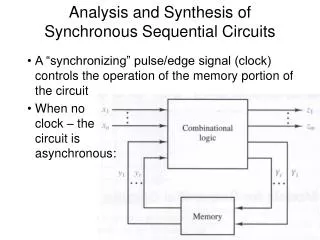
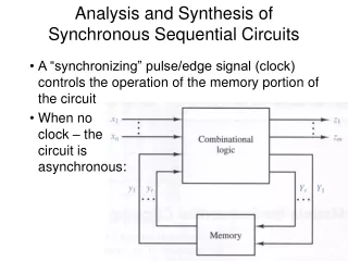
The Synchronous Sequential Circuit Model Figure 8.1
Mealy Machine Model Figure 8.2
Mealy Machine Timing Diagram -- Example 8.1 Figure 8.3
Moore Machine Model Figure 8.4
Moore Machine Timing Diagram -- Example 8.2 Figure 8.5
Analysis of Sequential Circuit State Diagrams -- Example 8.3 Figure 8.6
Timing Diagram for Example 8.3 Figure 8.7
Timing Diagram for Figure 8.8 (a) Figure 8.9
State Table and State Diagram for Figure 8.8 (a) Figure 8.10
K-Maps for Circuit of Figure 8.8 (a) Figure 8.11
Synchronous Sequential Circuit with T Flip-Flop -- Example 8.4 Figure 8.12
Timing Diagram for Example 8.4 Figure 8.13
State Table and State Diagram for Example 8.4 Figure 8.14
K-Maps for Example 8.4 Figure 8.15
Synchronous Sequential Circuit with JK Flip-flops -- Example 8.5 Figure 8.16
Timing Diagram and State Table for Example 8.5 Figure 8.17
K-Maps for Example 8.5 Figure 8.18
Generating the State Table From K-maps -- Example 8.5 Figure 8.19
Synchronous Sequential Circuit Synthesis Figure 8.20
Introductory Synthesis Example -- Example 8.6 Figure 8.21
Flip-flop Input Tables -- Example 8.6 Figure 8.22
Generating the JK Flip-flop Excitation Maps --Example 8.7 Figure 8.23
Clocked JK Flip-Flop Implementation --Example 8.7 Figure 8.24
Application Equation Method for Deriving Excitation Equations -- Example 8.8 Figure 8.25
Sequence Recognizer for 01 Sequence -- Example 8.9 Figure 8.26
Synthesis of the 01 Recognizer with SR Flip-flops Figure 8.27
Realization of 01 Recognizer with T Flip-flops Figure 8.28
Design of a Recognizer for the Sequence 1111 --Example 8.11 Figure 8.29
SR Realization of the 1111 Recognizer Figure 8.30
Clocked T and JK Realizations of the 1111 Recognizer Figure 8.31
Clocked JK Flip-Flop Realization of a 1111 Recognizer Figure 8.32
Design of a 0010 Recognizer Figure 8.33
Design of a Serial Binary Adder Figure 8.34
Design of a Four-State Up/Down Counter Figure 8.35
An Implementation of the Up/Down Counter Figure 8.36
Design a BCD Counter Figure 8.37 (a) and (b)
Design of the BCD Counter (con’t) Figure 8.37 (c)
Realization of the BCD Counter Design Figure 8.37 (d) and (e)
K-map For Y1 in Example 8.16 Figure 8.38
Robot Controller Floor Plan -- Example 8.17 Figure 8.39
Robot Controller Design Figure 8.40 (a) -- (e)
Robot Controller Realization Figure 8.40 (f)
Candy Machine Controller Design -- Example 8.18 Figure 8.41
Algorithmic State Machines (ASMs) Figure 8.42
ASM Representation of a Mealy Machine Figure 8.43
ASM Representation of a Moore Machine Figure 8.44
Eight-Bit Two’s Complementer ASM -- Example 8.19 Figure 8.45
Binary Multiplier Controller -- Example 8.20 Figure 8.46