Download
1 / 18
180 likes | 344 Views
SKA New Technology Demonstrator. Ray Norris CSIRO Australia Telescope National Facility. What is the NTD?. New Technology Demonstrator An MNRF-funded project: $2.535m MNRF $3.05m CSIRO $5.585m TOTAL Of which, $3.8m remains. What are we demonstrating?.

E N D
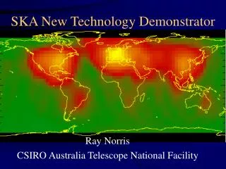
SKA New Technology Demonstrator Ray Norris CSIRO Australia Telescope National Facility
What is the NTD? • New Technology Demonstrator • An MNRF-funded project: • $2.535m MNRF • $3.05m CSIRO • $5.585m TOTAL • Of which, $3.8m remains
What are we demonstrating? • SKA technology in which Australia can play a key role (not just antennas!) • Credibility of Australia as an SKA host site • If possible, some key science outcomes.
Original NTD goals • Explore SKA technologies, especially • phased array • Luneburg Lens • Build two SKA mini-stations at Narrabri • Augment capability of ATCA
NTD outcomes so far • Luneburg lens project (see J Kot talk) • Potential commercial applications • Some phased array work • Now overtaken by Faraday, Pharos, etc. • System development • See white papers, etc.
Why refocus NTD? • Luneburg lenses no longer attractive for SKA • see ASKACC report • Within the budget, NTD cannot significantly enhance ATCA science capability while demonstrating SKA technology • CABB, MMIC are doing this • Opportunity to demonstrate the best (i.e. Australian) site for SKA • Recognition that SKA is not just about antennas • e.g. signal processing, data transport, calibration, software, RQZ
Recent NTD history • 2003: LOFAR showed that • WA is best site of those examined, at low frequencies • Such a site strongly influences technology (e.g. # of bits of sampling) • Growing international interest in WA as an SKA site • Early 2004: Australia withdrew from LOFAR • March 2004: ASKACC suggest a review of NTD • April 2004: “Vision Paper” supported by ASKACC sub-committee and AT Steering Committee • Now: proposal for implementation of that Vision Paper
NTD refocused:Build a technology demonstrator at Mileura, WA • Demonstrate the feasibility of remote operation of a radio astronomy facility in a very radio-quiet site • Demonstrate technology enabling a very wide field of view at low SKA frequencies • Pave the way for key science outcomes
Eventual goal: a facility demonstrating • Wide (>50°) FOV Antennas • Cylinders covering 700-1400 MHz • EOR phased-array tiles covering 80-200 MHz • Radio-quiet Zone • Infrastructure • Correlator • Software • Signal transport • Energy provision • A radio-quiet facility for testing other SKA technologies • Key science outcomes
Technologies examined • Antenna: • Review wide-field antenna technologies • Cylinder with >50° FOV at 700-1400 MHz • Small (~3m?) parabolas with same specs, as fall-back • MIT EOR/transient tiles: 80-200 MHz • Fibre data transmission • Beamformer/filterbank/correlator • Algorithms & software
Sample configuration studied 4 cylindrical reflectors, each 50m * 15m FOV 2° * 33° (after beamforming) 2000 dual-polarisation feeds 4000 LNAs 1000 first beamformers Analogue coax to correlator building 1000 filterbanks, each 1024 chan * 256 MHz 125 inputs to each beamformer 125 8 second beamformers 125 125 outputs from each beamformer 2 correlators, each 125 beams*12 baselines *1024 channels Plus: Software, Energy supply, Data Transport, control system, RQZ, other facilities, etc.
NTD Phase 1: July 2004 – April 2005 • Development (with SKAMP) of a line feed (700-1400 MHz) • Feasibility study & prelim design of cylinder antennas • Design of low-frequency antenna tiles (8-250 MHz) • Development of fallback options • Overall system design & costing • Ends with Preliminary Design Review (PDR) (MIT NSF grant outcome also announced ~ March 2005)
NTD Phase 2: May 2005 – June 2006 • Architecture and configuration selected • Detailed design and costing • Prototype subsystems • Establish site • Start installing EOR tile antennas • Ends with Critical Design Review (CDR)
NTD Phase 3: July 2006 – June 2007 • Construct small-scale demonstrator of cylindrical antenna? • Establish facility with EOR tiles • Paves way (subject to additional funding) for either: • Construction of SKA Phase 1 • Construction of HYFAR
Risk mitigation • Cylinder/line feed fails • Prototype line feed on SKAMP • Use small off-the-shelf parabolas • MIT/WA funding fails • Concentrate on cylinder/parabola • Build at Narrabri instead
Proposed budget (i.e. not yet allocated) Additional University partners may also participate & contribute