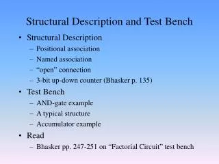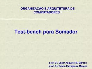
DQLPU Functional Test Bench
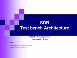
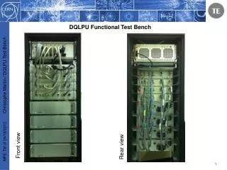
DQLPU Functional Test Bench. Front view. Rear view. Outline:. DQLPU crate (Local Protection Unit for the LHC Main Magnets). 1. 2. 3. 4. 5. 6. DQQDL => Redundant quench detectors based on analog measurement bridge ( M agnet AP erture ). 1. 2.

DQLPU Functional Test Bench
E N D
Presentation Transcript
DQLPU Functional Test Bench Front view Rear view
DQLPU crate (Local Protection Unit for the LHC Main Magnets) 1 2 3 4 5 6 DQQDL=> Redundant quench detectors based on analog measurement bridge (Magnet APerture) 1 2 DQHSU => Quench heater circuit supervision 3 DQCSU => Crate supervision 4 DQAMC => Fieldbus coupler 5 DQIPF => Fieldbus & programming connector (passive board) 6
Test Bench main requirements: • This test bench will perform a FUNCTIONAL test (not an hardware test...) • A hardware test verifies each component on a PCB board • A functional test verifies the behaviors of an assembled system • The whole assembled DQLPU crate will be tested • each individual board has been previously tested on its corresponding test bench • The GUI must be simple, non expert must be able to use this test bench • Thanks to the provided user manual, any team member should be able to run a test • Up to 4 DQLPU crates can be tested in one test sequence • not at the same time but one after the other
DQLPU Test Bench structure Like most of industrial test benches, the different elements of the DQLPU test bench are: • General Tester Crate • In the DQLPU test bench case, it’s a National Instrument PXI crate with different NI modules inside, this assembly is designated as the GTC • Test Controller Card • The TCC is the interface between the GTC and the device to test. It is generally used to adapt the different voltages. In the DQLPU test bench it is mainly used as a multiplexer • Device Under Test: • The whole DQLPU crate
DQLPU Test Bench resources • Hardware resources: • National Instrument PXI platform is used for the GTC • A simple TCC will ensure the Multiplexer function and all interconnections between the 4 DQLPU crates. There is no active electronic on this TCC ( the relays will be directly powered by the PXI relay driver module). • Software resources: • National Instrument LabWindows CVI is used • The embedded processor runs with Windows 7 • (Microsoft office is supported)
DQLPU DQLPU test bench overview • Common resources: • NI PXI 8106 controller • NI PXI 4110 PSU • NI PXI 6733 analog I/O • NI PXI 6221 general purpose DAQ • Individual resources: • NI PXI 2567 64-channel relay driver • DQAMC Worldfip connection
NI PXI-8106 Controller Ni PXI-8106 • - Intel core 2 Duo processor • - Works with Microsoft Windows Integrated IO • - 10/100/1000 Base TX Ethernet • - 4 Hi-Speed USB ports • - RS232 serial port • - IEEE 1284 ECP/EPP parallel port • - GPIB Controller • Middle range controller in terms of power and price • GPIB is very useful for industrial test benches connection • (the parallel port is used with former Xilinx Parallel 4 JTAG probe)
NI PXI 4110 PSU Triple-Output Programmable DC Power Supply Ni PXI-4110 • - 3 independent DC PSUs • - 1 x 0 → 6 V DC up to 1 A • - 2 x 0 → ±20 V DC up to 1 A (Ext PWR) • - 16-bit U and I set point • - 16-bit U and I read back function • for DQLPU T.B. : a pair of PXI 4110 is required • DQLPU current consumption can be • limited and can be read
NI PXI 4110 PSU Connection • All diodes on the motherboard can be tested • No insulation between ISO and COM voltages on the Test Bench
NI PXI 2567 64-channel Relay Driver Module Ni PXI-2567 • - Control up to 64 external relays • Works with internal or external power sources • 1.25 A for all channel with internal power • 600 mA per channel with external power • for DQLPU T.B. : 4 x PXI-2567 are required • Direct TCC connection with standard 78-pin D-SUB female connector • For DQLPU T.B. : • the total TCC relays consumption is < 1.25 A => no external power required
NI PXI 6733 Analog Output Ni PXI-6733 • - 8 independent analog output • - 16-bit output (after calibration) • - ±10 V DC output • Direct TCC connection with • SH68-68-EP shielded cable
NI PXI 6733 Analog Output connection • DQQDL A and B can be simultaneously tested
NI PXI 6221 General Purpose DAQ Ni PXI-6221 • - 24 digital I/O • Direct TCC connection with • SHC68-68-EPM shielded cable
GTC to TCC interconnection • These interconnections are realised only once during the test bench configuration. They are accessible from the front side.
TCC to DUT (DQLPU) individual interconnection • These interconnections must be realised each time a new DQLPU is inserted for test and are accessible from the rear side.
How to define the tests to execute on the DQLPU ? • 1) The key point is the knowledge of the DQLPU functionality. From the different board schematics, a “reverse engineering” has been performed and the global DQLPU functionality deduced. • 2) The test bench has no access to individual board connectors, since only the motherboard connectors are accessible. • Taking into account this restriction, specific paths have been identified to test most of the DQLPU functionality. • 3) After a review with the different design engineers, all relevant tests have been considered and have been clearly described in the document “DQLPU TEST PLAN”.
EDMS document “DQLPU TEST PLAN”
Test bench monitoring paths 4 1 2 3 CVI provides simulated parameters to the DQLPU under test 1 DQAMC sends monitoring data to the gateway via the FIP 2 Labview running on a desktop PC reads the value gathered by the gateway 3 CVI via data socket protocol communicates with Labview application 4 The FIP functionality is indirectly tested
DQLPU Power Supply tests (Common and Isolated) • DQLPU Common power supply
DQLPU Power Supply tests (Common and Isolated) • DQLPU Isolated power supply
DQLPU Power Supply tests details The 12 independent power supplies are individually tested. This test performs the following actions : Direct tests: • Check short circuit between the different power supplies (soldering, PCB …) • Check integrity of the 12 power diodes (mounting side, soldering …) • Each individually current consumption is measured, recorded and compared to defined thresholds (min & max) Indirect tests (monitoring path): • The 12 readback voltage values are compared to the real ones • The power diodes forward voltages are measured and compared to defined thresholds
DQQDL aperture measurement tests details The 4 MAP voltages are individually tested. This test generates a voltage between -80mV and 80mV on each simulated MAP. These voltages are below the DQQDL trigger thresholds (thus, no interlocks are generated) Indirect test (monitoring path): • The 4 readback voltage values are compared to the applied values
DQQDL HDS Firing relay tests details This function checks the real MAP voltage required to close the HDS firing relay on each DQQDL board. This test increases the simulated MAP voltage till the HDS firing relay is activated. The real value is precisely measured. Direct test : • Checks the integrity of the DQQDL HDS firing path ( threshold, relay …)
DQQDL Interlock relay tests details This function checks the capability of each DQQDL board to close the interlock relay. This test applies on the DQQDL MAP inputs a voltage higher than the maximum threshold. Direct test : • Checks the integrity of the DQQDL interlock path ( threshold, relay …)
DQHSU reading heater current tests details This function checks the readback capability of the DQHSU to read the 4 heater currents. This test applies a voltage on the different DQHSU “I IN” inputs. Indirect test (monitoring path): • The 4 readback current values are compared to the applied values
DQHSU reading heater voltage tests details This function checks the readback capability of the DHSU to read the 4 heater voltages. This test applied a voltage on the different DQHSU “V IN” inputs. Indirect test (monitoring path): • The 4 readback voltage values are compared to the applied values
DQLPU interlock tests details This function checks the integrity of the two interlock connectors mounted on the motherboard. A binary pattern is applied on one connector and then read back on the second connector. Direct test : • The sent pattern is compared to the readback pattern
LabWindows/CVI • Labwindows CVI is an ANSI C integrated development environment provided by National Instrument. • Like Labview, the implementation of Graphical User Interface is very easy to implement.
DQLPU test bench interface The whole DQLPU test bench is arranged around 3 distinct GUIs. • Initialisation GUI Prior to any test, a self test is executed on the whole test bench (GTC & TCC). The test is stopped if some errors appears during the self test
Help GUI This online help is intended to quickly allow the operator to fix minor hardware problems during initialisation, typically some cabling mistake.
Main GUI The main GUI is the most important one and is used to launch all tests. Only two tabs are necessary to control the full test bench.
Test list file concept The tests sequence and the associated parameters are extracted from an Excel file: • Function name : user friendly name of the test that must be executed • Short description : only used to gives information to the operator • Parameters : define the behaviours of the current test • Action on fail : the behaviour in case of errors
Advantage of the test list file • The operator can easy modify the sequence and behaviours of the tests without any knowledge in C programming and without having to recompile the whole test bench C code. • If the global test must be launched several times, the same test list file can be reused. • The test report is archived together with the test list file, so the conditions of the test can be easily retrieved. • The test list file avoids many setup errors: more easy to write a complete test sequence in an excel sheet that configuring many objects in different graphical panels.
Test report The test report is easy as possible. Microsoft word is used to realise this report. Each individual test adds a new line in the report after the previous one.
Conclusions • The test bench is based on EDMS document “DQLPU TEST PLAN”. The latter describes all relevant tests identified following an internal EP review. • In complement of the individual board tests, this functional test bench validates the DQLPU crate functionality. • Thanks to the concept of “Generic Test Bench” based on NI PXI, this type of test bench can be smoothly realised for another crate/system.