Download
1 / 58
580 likes | 709 Views
Phase II of the EVLA. Rick Perley EVLA Project Scientist. What is the Future for cm-wavelength Astronomy?. Any attendee of a recent AAS Meeting will know that astronomy is hardly in a state of decline.

E N D
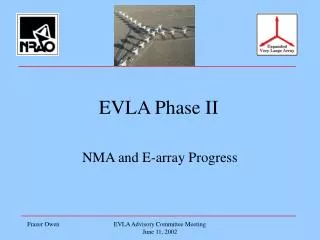
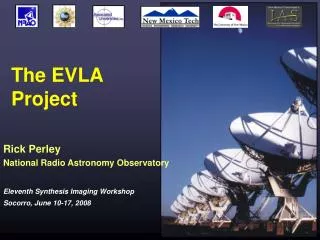
Phase II of the EVLA Rick Perley EVLA Project Scientist
What is the Future for cm-wavelength Astronomy? • Any attendee of a recent AAS Meeting will know that astronomy is hardly in a state of decline. • Exciting new results, particularly in the area of cosmic evolution, are regularly announced. • New instruments and missions fill the display booths. • What about radio astronomy? ALMA and CARMA speak well for millimeter-wave interferometry. • Is there a future for cm-wave astronomy? • The SKA would represent a major advance – but this is >10 years away, if it ever comes. • Is there an intermediate, and more practical and immediate vision? EVLA Advisory Committee Meeting September 8-9, 2003
Astronomy in the New Millennium • In 2001, the Astronomy and Astrophysics Survey Committee wrote in the executive summary of their report: The fundamental goal of astronomy and astrophysics is to understand how the Universe and its constituent galaxies, stars, and planets formed, how they evolved, and what their destiny will be. To achieve this goal, we must survey the Universe and its constituents, including galaxies as they evolve through cosmic time, and intergalactic gas as it accumulates the elements created in stars and supernovae, and the mysterious dark matter and perhaps dark energy that so strongly influence the large-scale structure and dynamics of the Universe. • The 2000 Decadal Committee went on to identify five key problems which ‘are particularly ripe for advances in the coming decade’. EVLA Advisory Committee Meeting September 8-9, 2003
The Five Key Problems • Determining the large scale properties of the Universe: the amount and distribution of its matter and energy, its age, and the history of its expansion. • Studying the dawn of the modern Universe, when the first stars and galaxies formed. • Understanding the formation and evolution of black holes of all sizes. • Studying the formation of stars and their planetary systems, and the birth and evolution of giant planets. • Understanding how the astronomical environment affects Earth. EVLA Advisory Committee Meeting September 8-9, 2003
Resolving Cosmic Evolution • The Committee placed a clear emphasis on understanding the evolution of the components of our universe. • Radio astronomy can and should have a prominent role in addressing all of these ‘key problems’. • Although detection of such objects and processes is good, imaging them is better. • What kind of radio telescope is needed for research into these forming systems? EVLA Advisory Committee Meeting September 8-9, 2003
Telescope Requirements • 10 milliarcsecond resolution. This corresponds to: • 1 AU at distance of nearby star-forming regions. • 100 pc or less for galaxies *anywhere* in the distant universe. • < 1 mJy/beam sensitivity. This will enable study of: • Accretion disks around forming stars (Tb ~ few x 100 K) • Ionized gas and SNRs in galaxies (Tb ~ 100 – 1000 K) • Jets from stars and black holes. • Imaging over a range of angular scales up to 10,000. • The distant universe will be as complex as the nearby universe • These capabilities over a very wide frequency range. • Hundreds of MHz to hundreds of GHz. • We want all of this soon! (Very Important!) EVLA Advisory Committee Meeting September 8-9, 2003
The EVLA will meet these Requirements • The only way to get these capabilities on a less than 1 decade timescale is to build upon the existing VLA. • Phase I of the EVLA will provide the order-of-magnitude improvement in sensitivity necessary to meet the sub-microJy sensitivity requirement. • Phase II of the EVLA will expand the array by an order of magnitude to provide both the resolution and baseline coverage requirements. • Both the EVLA and ALMA are needed to provide the frequency coverage. • The Decadal Committee recognized the EVLA’s crucial role, and gave the project its 2nd highest recommendation amongst major ground-based new facilities. EVLA Advisory Committee Meeting September 8-9, 2003
The Committee’s Recommendation They wrote: The Expanded Very Large Array (EVLA) – the rebirth of the VLA, the world’s foremost centimeter-wave telescope – will take advantage of modern technology to attain unprecedented image quality with 10 times the sensitivity and 1000 times the spectroscopic capability of the existing VLA. The addition of eight new antennas will provide an order-of-magnitude increase in angular resolution. With resolution comparable to that of ALMA and NGST, but operating at much lower frequencies, the EVLA will be a powerful complement to these instruments for studying the formation of protoplanetary disks and the earliest stages of galaxy formation. EVLA Advisory Committee Meeting September 8-9, 2003
EVLA Phase II Key Components • New Mexico Array (NMA) to increase resolution. • 8 new `VLBA-style' antennas, each with 10 frequency bands. • Upgrading two VLBA antennas (PT and LA) to EVLA standards. • Connection by rented fiber to expanded WIDAR correlator. • Low-Frequency Capability: • to extend frequency coverage to include 240 to 1200 MHz band. • `E'-Configuration: • Construction of 20 new antenna pads at 'Wye' center. • Compact array with ~250 meter maximum spacing. • Incorporation of VLBA within EVLA • Canadian correlator will replace both VLA and VLBA correlators. • VLBA and EVLA run as a single operational structure. EVLA Advisory Committee Meeting September 8-9, 2003
EVLA High Resolution Science:Star Formation: Outflows and Cores G192.16-3.82 – massive prototstar in Orion 80 AU • Sub-AU imaging at Taurus • Thermal outflows: ubiquitous & essential part of star formation • carry away angular momentum and much of the mass • may halt accretion - pump energy into cloud • Central regions of pre-main sequence cores EVLA Advisory Committee Meeting September 8-9, 2003
EVLA High Resolution Science:Imaging Distant Galaxies • M82 – a nearby star-forming galaxy, seen by VLA + MERLIN. • EVLA will give 10 x the resolution and 10 x the sensitivity. • Could resolve such objects anywhere in the Universe. EVLA Advisory Committee Meeting September 8-9, 2003
EVLA Low Frequency Science:Evolution of Atomic Gas Single, very deep integration, covering 750 to 1200 MHz: • z=0.2 to 1 in one observation • Simultaneously covers OH maser emission from z=0.33 to 1.6! • unbiased census of atomic gas over half the age of the Universe • kinematics & merger rates • absorption line surveys & imaging • constrain evolution of physical constants EVLA Advisory Committee Meeting September 8-9, 2003
EVLA E-Config. + GBT Science:Imaging galaxy clusters at arbitrary redshift S-Z effect allows imaging of large-scale cluster structures. (l) Hydro-code simulation of S-Z effect for a modest galaxy cluster at z=1, (m) 30 GHz simulated observation: 10 arcsec , 15 mK sens., 6 hr + GBT (r) Convolved to 22 arcsec, and 1.7 mK sensivity. • 50 kpc resoloution images, at any redshift. Can map gas density at any redshift. • on-going examples of hierarchical structure formation EVLA Advisory Committee Meeting September 8-9, 2003
A Telescope for all Astronomers • Of course, the EVLA was not specifically designed to do research on cosmic evolution. • The goal has always been the same as that for the VLA – a superbly sensitive, powerful, and flexible telescope to do research for all branches of astronomy. • The proposal contains 70 pages of science examples, taken from a wide range of research areas. • Most assuredly, the best science will come in areas not anticipated by us in this survey. EVLA Advisory Committee Meeting September 8-9, 2003
Research Topics • From the proposal appendix. Find your subject of interest • Solar system bistatic radar • Synchrotron emission from giant planets • Imaging cometary comae • Imaging spectroscopy of solar radio bursts • Turbulence in the interplanetary medium • Imaging of stellar photospheres, outflows, and shocks • Thermal winds in early-type stars • Masers on the Asymptotic Giant Branch • Resolving active stars • Unraveling Galactic novae • Tying the radio with the optical reference frame EVLA Advisory Committee Meeting September 8-9, 2003
And more … • Tracking Stellar flares • Brown dwarfs • Extrasolar planets • Pulsars • HII regions in the Milky Way • Spectral Imaging of SNRs • Masers and SNR shocks • Finding the missing SNRs • Spectral studies of the Galactic center • Gas motions and Stellar masers • Tracing the Ionized gas and galactic magnetic fields • Thermalized lines of the ISM EVLA Advisory Committee Meeting September 8-9, 2003
And yet more … • Discrete sources in nearby galaxies • Disentangling thermal and non-thermal emission • Galaxy Halos • Neutral Hydrogen in normal galaxies • Radio jets and radio galaxies • Source evolution and impact on environment • Diffuse sources in clusters of galaxies • Gravitational lenses • Particle acceleration in the Universe • Deep surveys • Studies of individual Hi-z radio galaxies • Redshifted absorption lines EVLA Advisory Committee Meeting September 8-9, 2003
New Mexico Array • Design Goals: • High sensitivity on long baselines • Good imaging characteristics • Site locations near existing fiber, roads, power. • Same frequency coverage as Phase I antennas. • Interoperability with the VLBA. • Affordable cost and short timescale. • Configuration Studies • Site searches done by F. Owen, C. Walker and C. Wade • Imaging characteristics by Aaron Cohen (NRL) and me. EVLA Advisory Committee Meeting September 8-9, 2003
Sensitivity Requirementsfor new EVLA Stations • Sensitivity is a key goal. We will always be sensitivity limited. • These values are based on science goals, tempered by a careful dose of reality. EVLA Advisory Committee Meeting September 8-9, 2003
Location of the NMA Antennas • The new antennas are shown in white. • Upgraded VLBA antennas are in yellow. • Proposed new location of Los Alamos antenna is SE of Albuquerque. • All sites are on public land, with road access, nearby power and fiber. EVLA Advisory Committee Meeting September 8-9, 2003
UV-Coverage for NMA • Left panel is for the 10-antenna NMArray. • Right panel is the full 37-antenna EVLA. • Use of BW Synthesis completely fills in the UV plane. EVLA Advisory Committee Meeting September 8-9, 2003
Imaging Fidelity • Left panel shows fidelity for the full 37-antenna EVLA. • Trial source is 170,000 synthesized beam areas. • Right panel shows fidelity for the NMArray + 1 VLA. • Trial source is 29 synthesized beam areas. EVLA Advisory Committee Meeting September 8-9, 2003
Choice of Element • We considered both 25-meter, and smaller (12-meter) reflectors. • The 25-meter design is the current choice: • Meets the antenna sensitivity requirements • Well known design, well known cost • Results in homogenous array (a very desirable feature for us) with same electronics for all antennas. • Reduces fiber rental and fiber electronics costs. • Greatly reduces post-processing and imaging costs. • All are important, but the last point is ultimately the most important. EVLA Advisory Committee Meeting September 8-9, 2003
Processing Costs where For a constant collecting area To avoid BW losses To avoid time smearing To avoid a 3-d transform Simply a guess EVLA Advisory Committee Meeting September 8-9, 2003
Processing Overload! • This simple analysis leads to the dependency: • How bad can this be? Really, really bad! • For a 37-antenna EVLA of 25-meter antennas, the required • data-rate for full-field imaging at 1 – 2 GHz band is well in excess of 2 GB/sec. This leads to > 50 TB data sets in 12 hours. • Projections are (using Moore’s law) that we’ll only be able to properly process these databases in ~ 2017. • The time is not right to consider going to smaller antennas. EVLA Advisory Committee Meeting September 8-9, 2003
EVLA Sensitivity1-s, 1 hour, Stokes I EVLA Advisory Committee Meeting September 8-9, 2003
EVLA Sensitivity at 34 GHz12 hours, 1-s, Stokes I EVLA Advisory Committee Meeting September 8-9, 2003
NMA 86-GHz Capability The 10-element NMA will have outstanding sensitivity on its own at 86 GHz. EVLA Advisory Committee Meeting September 8-9, 2003
Expansion to Low Frequencies • Primary Requirements: • Continuous frequency coverage downwards from 1.2 GHz to 240 MHz. • Capability to go to lower frequencies, if desired. • Very high sensitivity in upper half (700 to 1200 MHz) is critical. • Very high linearity (for RFI tolerance and solar observing) • Good primary beam circularity, to minimize computational costs in deep full-field imaging. EVLA Advisory Committee Meeting September 8-9, 2003
Implementation Plan • VLA’s Cassegrain optics antennas are difficult to modify for these frequencies. • Subreflector is small (requires large (7 l) secondary feed) • Subreflector cannot be withdrawn far enough to expose prime focus. • Either we must remove the subreflector by some means, or employ off-axis feeds. • We have considered focal plane arrays. (Brisken, EVLA Memo #53). • Not practical in front of subreflector • Could be considered beside subreflector (off-axis), but early studies indicate insufficient G/T above 700 MHz. • Has potential for low frequency application in off-axis position. • More study is needed, as the technology develops EVLA Advisory Committee Meeting September 8-9, 2003
Baseline Approach • The baseline plan is to implement a rotating mount to swing the subreflector out, and rotate in appropriate feeds. • The horizontal quadrupod legs replaced with splayed rods. • Subreflector rotates through the gaps. • The 700 – 1200 MHz feed will be cryogenically cooled for maximum G/T. • Two lower frequency feeds do not need cryogenic cooling. EVLA Advisory Committee Meeting September 8-9, 2003
Low-Frequency solutions • The left panel shows the rotating mount. The ‘pizza boxes’ represent low frequency feeds. This is the baseline plan. • The right panel shows a possible offset FPA (outline). Such an approach needs considerable technical development. EVLA Advisory Committee Meeting September 8-9, 2003
An FPA Approach These show the diffracted images of a point-source at an angle of 7.2 degrees from the optical axis, at 300, 500 700 and 1000 MHz. A single feed can only cover the central lobe. An FPA can (in principle) collect much more energy. See Memo 53 (Brisken) for details. EVLA Advisory Committee Meeting September 8-9, 2003
FPA Problems However, the coarseness of the sampling makes it difficult to make a circular beam. FPAs cannot be cryogenically cooled, so there is a significant increase in Tsys compared to single-horn feeds. EVLA Advisory Committee Meeting September 8-9, 2003
Wide-Field Imaging(E-Configuration) • The goal of this component is to provide a capability for imaging low-surface brightness objects larger than the antenna primary beam. • Brightness temperature goal of ~20 mK for resn ~ 250/uG arcseconds. • Surface brightness sensitivity relation: h = system efficiency f = packing fraction High packing fraction is clearly desirable! EVLA Advisory Committee Meeting September 8-9, 2003
Design Constraints • In fact, any super-compact VLA configuration will require external data to fill in the ~30 meter hole at the center of the (u,v) plane. (This is inevitable if the goal is to image objects larger than the primary beam!) • This component must be thought of as a combination of the GBT (or other large single antenna) and the E-config. • Configuration design done by L. Kogan and F. Owen. • Make maximum use of existing pads. • Avoid locations which will interfere with EVLA fiber/power/road communications. • Minimize shadowing (especially in the south). • Randomize u-v coverage (lowers the in-beam sidelobes) EVLA Advisory Committee Meeting September 8-9, 2003
E-Configuration Design • Left panel shows the standard E-configuration. The filling factor is about 0.25. Red dots are existing stations. Dot width = 25 meters. The packing fraction is about 0.25. • Right panel shows a possible northward extension to reduce shadowing at southern declinations. Red dots are added stations. EVLA Advisory Committee Meeting September 8-9, 2003
Imaging: E vs. D • A smooth u-v distribution is important for high fidelity imaging. • The left panel shows the D-configuration coverage to 250 m. • The right panel shows the E-configuration coverage. EVLA Advisory Committee Meeting September 8-9, 2003
E-Config. Sensitivity, etc. EVLA Advisory Committee Meeting September 8-9, 2003
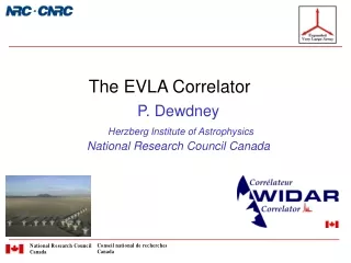
Integration with VLBA • The WIDAR correlator can input recorded data – from tape or disk. • One WIDAR correlator input can handle 2 antennas at ¼ (4 GHz) bandwidth, or 4 antennas at 1/16 (1 GHz) bandwidth • The correlator must be expanded from 32 to 40 stations for Phase II. • Extra 3 inputs can handle 6 stations at 4 GHz, or 12 stations at 1 GHz. • An essentially unlimited number of combinations can be accommodated, e.g.: • 37 realtime @ 16 GHz + (8 VLBA + 4 others) disk-based @ 1 GHz. • 27 realtime @ 16 GHz + (18 NMA/VLBA + 8 others) disk-based @ 4 GHz. • We thus plan to combine the EVLA and VLBA operations groups, and use a single, WIDAR, correlator. Both the VLA and VLBA correlators will be decommissioned. • NB Phase II proposal will outfit NMA antennas with Mk 5 recorders, but not the eight remaining VLBA antennas. EVLA Advisory Committee Meeting September 8-9, 2003
`Astronomical Discovery Space’ The Frequency-Resolution Plane Coverage of various future/current instruments is shown. Upper limit set by diffraction, or detector. Lower limits set by telescope or antenna field of view. 10 mas 10 mas EVLA Advisory Committee Meeting September 8-9, 2003
EVLA – VLA to Phase I Discovery Space for radio astronomy This shows the coverage after completion of ALMA and EVLA Phase I. Red dots are ‘evolution lines’. More coverage needed. EVLA Advisory Committee Meeting September 8-9, 2003
EVLA – Phase I to Phase II This shows the coverage after completion of Phase II EVLA Advisory Committee Meeting September 8-9, 2003
Discovery Brightness The same figure, but with the lines of brightness temperature superposed. EVLA Advisory Committee Meeting September 8-9, 2003
Why both EVLA and ALMA? • Non-thermal processes emit at cm-wavelengths • Low dust opacity on long-wavelength side. • Cosmic expansion shifts spectrum to longer wavelengths. • EVLA and ALMA could detect and resolve Arp220 to z = 32! • Both instruments are needed to understand evolution of the components of our Universe EVLA Advisory Committee Meeting September 8-9, 2003
ALMA + EVLA • A good example of how ALMA and the EVLA will complement each other. • Redshifted emission from various CO transitions. EVLA Advisory Committee Meeting September 8-9, 2003
Computing Issues • Phase II will be operated using the same essential software as Phase I. • Imaging methodologies for Phase II will be the same as Phase I. • Major impact overall will be rate and volume of data, and the cost of the additional post-processing. • NRAO is not solely responsible for post-processing needs – but the fraction we need to have in house is not easy to assess. EVLA Advisory Committee Meeting September 8-9, 2003
Additional Computing Requirements • In e2e (end-to-end): • Minor impact in proposal preparation/submission and observation file preparation, and on telescope scheduling. 3.5 FTE-years • Minor impact on data archiving/export (up to 2012). 2 FTE-yr. • Moderate effort on pipeline processing. 3 FTE-years. • In M&C: • Implementation of NMA antennas will require moderate additional effort to design, observing layer, and antenna control subsystem. 10 FTE-years in total. • Moderate effort required for implementation of WIDAR for VLBA. 9 FTE-years. • Minor changes for Low-Freq. and E-Config. 2.5 FTE-yr. EVLA Advisory Committee Meeting September 8-9, 2003
Additional Computing Requirements (cont.) • Correlator expansion: • Must increase inputs from 32 to 40. • This requires an increase in CBE capability. $500K + 1 FTE-yr. • Initial output rate of 25 MB/sec (2008) selected from estimate of archiving and pipeline costs, and by capabilities of post-processing. This can be increased relatively easily! • Staged data rate plan: Go to 250 MB/sec in 2012, and 1.6 GB/sec by ~2017. Timescales set by Moore’s law applied to archiving and post-processing. EVLA Advisory Committee Meeting September 8-9, 2003
Post-Processing • Staged opening of the data tap should permit us to utilize Moore’s law to `catch up to our new correlator’ by 2017. EVLA Advisory Committee Meeting September 8-9, 2003