SNS Ring TiN Coating Experience
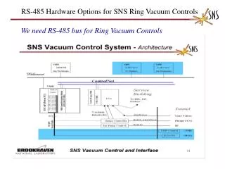
SNS Ring TiN Coating Experience. CERN Anti E-Cloud Coating Workshop Oct 12-13, 2009 by M. Plum, Ring Area Manager. Chopper system makes gaps. 945 ns. mini-pulse. Current. Current. 1 ms macropulse. 1ms. SNS Accelerator Complex. Accumulator Ring. Collimators.

SNS Ring TiN Coating Experience
E N D
Presentation Transcript
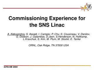
SNS Ring TiN Coating Experience CERN Anti E-Cloud Coating Workshop Oct 12-13, 2009 by M. Plum, Ring Area Manager
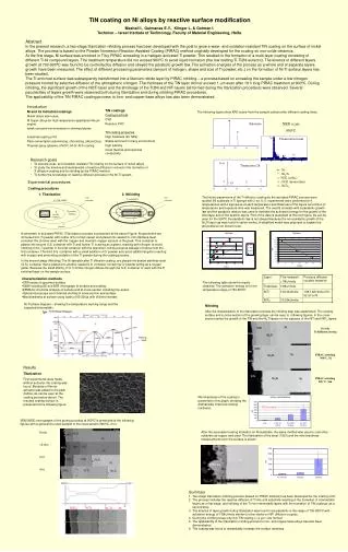
Chopper system makes gaps 945 ns mini-pulse Current Current 1 ms macropulse 1ms SNS Accelerator Complex Accumulator Ring Collimators Accumulator Ring: Compress 1 msec long pulse to 700 nsec 1 GeV LINAC Front-End: Produce a 1-msec long, chopped,H- beam Extraction Injection RF 1000 MeV RTBT 2.5 MeV HEBT Front-End LINAC Liquid Hg Target M. Plum -- AEC'09 -- Oct. 12-13, 2009
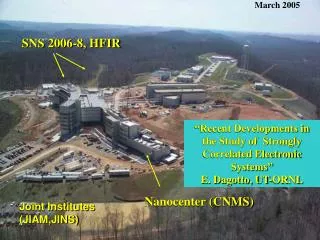
Beam power ramp up • Status: • Production beam with up to ~1.1e14 ppp (18 uC). • Full design intensity demonstrated at 1 Hz. October 1, 2006 to October 5, 2009 M. Plum -- AEC'09 -- Oct. 12-13, 2009
The SNS Accumulator Ring • Design ring parameters: • 1 GeV beam • Intensity: 1.51014ppp (24 uC) • Working point (6.23,6.20) • Ring circumference – 248 m • Space charge tune shift – 0.15 e-pmitigating features at SNS: • Vacuum chambers coated with TiN to reducesecondary electron yield • Solenoids in the collimation region • Clearing electrode near the stripper foil • BPMs can be biased to use as clearing electrodes • Robust dual harmonic RF system which can help keep the gap clean • Beam in gap kicker • Active damping system M. Plum -- AEC'09 -- Oct. 12-13, 2009
Status of electron control and measurement in the SNS Ring • All vacuum chambers TiN coated except: • ~7.1 m in RF straight for IPM and electron beam profile monitor development • ~2.2 m in collimation straight for active damping system development • ~2 m in vicinity of primary stripper foil, due to Al over-coating • Clearing electrode by primary foil • Powered for first time on Oct. 6, 2009 • Solenoid winding in collimation straight • Not powered M. Plum -- AEC'09 -- Oct. 12-13, 2009
Status of electron control and measurement in the SNS Ring (cont.) • BPM electrodes that can be biased • Present electronics do not allow biasing • Beam in gap kicker system • Not installed • Active damping system • Under development • RFA electron detectors • Have some very preliminary data M. Plum -- AEC'09 -- Oct. 12-13, 2009
Hseuh et al., Ecloud04 workshop M. Plum -- AEC'09 -- Oct. 12-13, 2009
Example of e-p instability data BPM sum gap BPM signal (mm) 700 turns gap high freq. oscillation near tail of bunch (From S. Cousineau et al., HB2008) M. Plum -- AEC'09 -- Oct. 12-13, 2009
Example of instability frequency Vertical Horizontal • Instability frequency: 60 – 100 MHz. • Vertical preceded horizontal by ~200 turns. (From S. Cousineau et al., HB2008) M. Plum -- AEC'09 -- Oct. 12-13, 2009
Summary of 2008 e-p data (From S. Cousineau et al., HB2008) M. Plum -- AEC'09 -- Oct. 12-13, 2009
Experiment vs theory • Measurements show that thee-p instability is present at charge intensities as low as 3e13 ppp (one fifth full design intensity, 24 kV of h=1 and 16 kV of h=2 RF) • On one occasion so far at full design intensity (1.5e14 ppp), measurements showed that instability can be controlled with Ring RF. (42 kV of h=1, 20 kV of h=2 RF). • Note that ~4.6% of Ring is uncoated. • Based on analytical and computational studies, and comparisons with LANL’s PSR, with no TiN coating • Stable up to 2e14 ppp for h=1 RF of 15 kV [Blaskiewicz et al., PRSTAB 2003] • Computational simulation including effects of TiN coating • Stable up to 2e14 ppp for h=1 RF of 13 kV [Shishlo et al., EPAC06] M. Plum -- AEC'09 -- Oct. 12-13, 2009
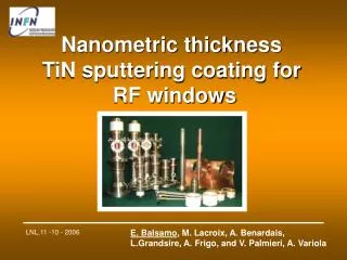
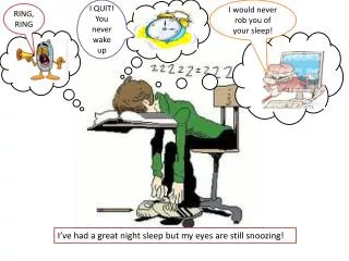
SEY of st. steel and TiN vs. scrubbing Copied from M. Nishiwaki and S. Kato, ECLOUD’07 SNS Ring beam pipes are 316L or 316LN stainless steel, bellows are Inconel 625 M. Plum -- AEC'09 -- Oct. 12-13, 2009
TiN summary • With ~95.4% of our ring coated with TiN, we have seen the instability at about one fifth of design intensity • Theory predicts no e-p instability up to 30% greater than design intensity • PSR experience: TiN coatings sometimes help, sometimes not until after scrubbing [R. Macek et al., ECLOUD ’04 & PAC03] • SNS vacuum chambers were exposed to air for months prior to installation, so our TiN started out unscrubbed, and may still be unscrubbed • Secondary emission yields of stainless steel and TiN seem to be about the same, before and after scrubbing • Is TiN coated stainless steel really better than just plain stainless steel? M. Plum -- AEC'09 -- Oct. 12-13, 2009
Future plans • Continue to develop active damping system • 400 W, 3to 300 MHz, each plane • Complete purchase of TiN coating system • $339k from Kurt J Lesker Co., due ~Jan. 2010 • Continue to get all chambers TiN coated • Continue to develop diagnostics and characterize electrons in ring • RFA electron detectors • Microwave plasma measurements • Determine effectiveness of TiN coating M. Plum -- AEC'09 -- Oct. 12-13, 2009
Electrons in vicinity of stripper foil Convoy electrons from a 1 GeV H− beam have 545 keV energy, gyroradius 12 mm, period 0.29 ns, pitch 16-23 mm. Center of circular motion moves ~14 mm downstream and ~5 mm beam left. Electrons are collected in an “electron catcher”. A 1 MW beam has ~1 kW power in the convoy electrons. M. Plum -- AEC'09 -- Oct. 12-13, 2009
Electron catcher and clearing electrode Water cooled carbon-carbon wedges Undercut prevents secondary electrons from escaping +/-20 kV biasing system Inlet and outlet water cooling lines have thermocouples, read out by EPICS and archived M. Plum -- AEC'09 -- Oct. 12-13, 2009
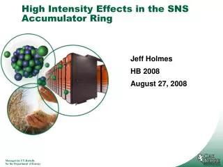
Electron catcher boroscope image Al coating Electron impact M. Plum -- AEC'09 -- Oct. 12-13, 2009
Graphitization at top of vacuum chamber Could be reflected convoy electrons or trailing-edge multipactoring 152 mm ~24 mm Clearing electrode M. Plum -- AEC'09 -- Oct. 12-13, 2009
Summary • e-pinstablility is present in SNS ring at intensities as low as 3e13 ppp (one-fifth design intensity). Theoretical work prior to commissioning predicted no e-p instability up to 30% greater than the design intensity. • e-p instability can be controlled with ring RF system up to full design intensity of 1.5e14 ppp (one time only) • Results from TiN coating are mixed – is it really better than just stainless steel? Note that ring still has ~11.3 m (4.6%) with no TiN coating. • Attempting to coat everything with TiN has been expensive and has caused installation delays. It will be interesting to determine if it has been worth it. M. Plum -- AEC'09 -- Oct. 12-13, 2009
Thank you for your attention! M. Plum -- AEC'09 -- Oct. 12-13, 2009
Backup slides M. Plum -- AEC'09 -- Oct. 12-13, 2009
SNS injection schematic • Closed orbit bump of about 100 mm • Merge H- and circulating beams with zero relative angle • Place foil in 2.5 kG field and keep chicane #3 peak field <2.4 kG for H0 excited states • Field tilt [arctan(By/Bz)] >65 mrad to keep electrons off foil • Funnel stripped electrons down to electron catcher • Direct H- and H0 waste beams to IDmp beam line M. Plum -- AEC'09 -- Oct. 12-13, 2009
Graphitization Example of graphitization by multipacting electrons in SRBM11 at PSR. This is not a thermal effect! (R. Macek, HB2008 & private comm.) M. Plum -- AEC'09 -- Oct. 12-13, 2009