Download
1 / 21
210 likes | 370 Views
Linac3 and GTS-LHC ion source. R Scrivens, D Kuchler, IEFC Workshop 2011. Outline. Schedule and Performance The Source Other Linac Issues (not exhaustive) New ions Final remarks. Schedule. Start of operation: 03/05/2010

E N D
Linac3 and GTS-LHC ion source R Scrivens, D Kuchler, IEFC Workshop 2011
Outline Schedule and Performance The Source Other Linac Issues (not exhaustive) New ions Final remarks
Schedule Start of operation: 03/05/2010 2 weeks of setup to prepare for the vacuum desorption experiment 3 weeks vacuum desorption experiment 8 weeks of source and Linac setup and MD’s Beam to LEIR: 09/08/2010 17 weeks operation for the setup of the injector chain and the physics in the LHC Beam to LHC: 04/11/2010 Beam stop in LHC: 06/12/2010 In total 30 weeks of operation
Performance • Beginning of the run had stable and intense beam, sufficient for EARLY and NOMINAL (produced by LEIR, NOMINAL with more injections that wanted). • Uptime calculated as 96% for LHC ion run, but very dependant on the methodology (source was in fault for 24h before the ions went to LHC, lower performance not explicitly marked).
Performance • Plot shows extreme values as noted in the elogbook (values due to obvious problems were excluded) • Week 36 only one value noted • Weekend between week 47 and 48 the intermediate electrode was short circuited, source and Linac had to be retuned to maintain some beam. Tried to limp to the end of the ion run with no oven refill, unsuccessfully. • Other variations of the intensity are related to source tuning and status of the stripper.
The Source Injection region Solenoids Hexapole Extraction Plasma Chamber Ovens HT region
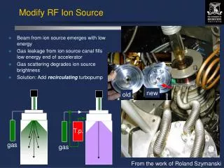
The Source • 2010 run made with a stainless steel plasma chamber and 14.5GHz microwaves . • Stainless steel chamber improved the source stability dramatically. • SS chamber produced high levels of xrays around the source. 18GHz caused higher radiation levels still, so remained at 14.5GHz. • No damage found afterwards in this plasma chamber, ordering of a spare chamber on its way • Good beam performance (for a high charge state metal ion, high intensity ECR ion source).
Source Tuning • The source often requires tuning. This can be from several times per day, or in the best case just a systematic increase in oven power every 24 hours. • Any disturbance to operation (trip of source supplies, water perturbation etc) often requires retuning over several hours. • Source performance moves away from optimal. This can be seen as a lower intensity, or intensity fluctuations. No controlled parameters have changed. • Adjustments are made to the 3 solenoid coils (<2% adjustments on the outer solenoids, ~20% adjustments on the central solenoid), empirically. • The microwave power and biased disk voltage are empirically adjusted. • Vary working pressure (1% variation in measured pressure can have a dramatic effect on source performance). A feedback loop stabilizes the pressure. • Increase Pb oven heating – this is usually done daily. It is only increased further if several source tunings have been needed. The thermal mass of the oven means increased heating takes 10 minutes to have any visible effect, and an hour to stabilize. Over heating the ovens can cause the Pb to melt and flow out, emptying them quickly. *
Oven oven • Oven refill takes around 3 hours to refill, and 28 hours to achieve stable beam production. This recovery time is necessary for 1 or 2 ovens being refilled. • Each oven is filled with up to 500 mg of 208Pb. • Oven heating is regulated on electrical power. V and I are logged locally. Two ovens operational The first oven filling lasts for around two weeks, the second for only one week (due to plasma heating of the oven) In 2010 only the first oven was used, the second one was used as hot spare in case of problems The change over between the two ovens is normally transparent to the operation, it takes several hours to bring up the second oven to operational conditions (big thermal mass) Mechanical movement of the oven disturbs the source vacuum and needs several hours of recovery time afterwards (pressure feedback control). Each action on the ovens requires a beam stop and recovery.
Oven oven Filament heater Crucible *
Oven Improvements for Operation Is it better to schedule a refill every 2 weeks, or be flexible and refill with one day’s notice (possibly up to 3 weeks running)? New oven filling method foreseen for this year: preparation of the crucibles offline, cast fill the crucible with molten Pb (presently metallic lead pieces are pressed into the crucible) Should result in more lead available per oven, but this does not guarantee a longer operational time (crucible can be emptied only ~80% in operation, opening of the oven closes up over time with lead oxide) There is no space to integrate a third oven into this source. Oven length or diameter could be increased. Design and production needed, with ~2 months of testing. BUT: We do not think this will get us to >4 weeks of operation for LHC! Already, better scheduling can probably limit us to 1 stop to refill in an LHC ion run.
Intermediate electrode • The intermediate electrode is connected in the vacuum with a kapton coated wire. • The wire sees a part of the beam and the kapton is burned away over time. The bare wire can than touch the vacuum chamber and create short circuit. The insulator of the feed through also suffers from a metallic coating. • New wire with a better insulation foreseen. In addition routed in a copper tube where possible. • Insulator moved further away from the beam axis. • If this modifications are not sufficient a preventive maintenance has to be done. Interventions are fast, but pump down and restarting causes a >2day stop. To HT feed through (-2kV) *
18 GHz operation • Not much experience up to now with 18GHz operation due to limited MD time. • Reminder: No improvements found compared to the 14.5GHz operation in the first tests. The theoretical possible high plasma density due to the higher frequency does not include the beam extraction and beam transport. So even if there are more ions available with higher frequencies, this does not mean necessarily that we get more beam out of the Linac. • Tuning of the wave guide between generator and HT break is still an open issue. Two different tuning possibilities tested without success (S-H-tuner, home made stub tuner). • The use of the stainless steel plasma chamber tripled the needed microwave power in the 14.5GHz case. If this is also valid in the 18GHz case, there may be not sufficient power from the generator available (Pmax=2.4kW). • Studies foreseen before the startup this year. • Frequency mixing is also an option that has to be studied (14.5GHz + 18GHz). • It is very likely that this year’s run will be done also with the 14.5GHz generator.
Source Spares * • The vast majority of spare parts are available, including the most expensive items (e.g. hexapole, solenoid coils, ovens and canes). • Spares in preparation: • SS plasma chamber. • 18GHz klystron. • Injection flange (discussing with EN/MME). • Missing spares with a risk: • Some internal insulators… • Overall the situation for spares is as good as the Linac2 source.
Vacuum system • ITL section direct after the source was modified in the shutdown 2009/2010 due to a recurring leaking bellow (due to beam erosion). A second iteration was needed, and this modification will be installed before the start of the run. • During the inspection of the spectrometer chamber a large amount of powder and flakes were found. It is mainly steel from the surface. In this region most of the separated charge states, especially oxygen, is lost. • A yearly cleaning campaign will be done by the vacuum team to avoid the accumulation of powder and flakes in the chamber. Risk is only that flakes can make a beam obstruction (the vacuum chamber is VERY THICK). *
Stripper • More than one time there was a reduction in intensity injected into LEIR, that could be corrected by exchanging the stripper foil. Insufficient systematic beam measurements from before and after to understand why. Needs more study in 2011. • The stripper mechanism is orphan. It includes bellows for which there are no spares. Request needs to be made to consolidation for ~250kchf. The stripper mechanism holds 4 frames with up to 4 foils in each. Last year we installed 8 foils with 75µg/cm2, 4 of them annealed and 4 non-annealed; and as a safety measure 2 foils with 100µg/cm2. We learned during the run that there is an average performance difference of 10-20% between the two types. We will use for this reason this year only non-annealed ones. And we will prepare a complete set of 16 foils to have sufficient spares. The stripper life time depends a lot on the duty cycle. Two weeks of operation with 650µs pulse length (instead of the standard 200µs) for the vacuum desorption experiment destroyed one foil.
Other Linac Systems * Due to the change of the material of the plasma chamber the radiation from the source went up. The shielding could only partial improved last year. This will be completed before this years run. The SEM grid ITL.MSG02 after the spectrometer found broken two times last year. It seems it see too much beam in the parking position. BI is working on a modification. The RF power loop of tank 3 and of the RFQ were leaking at the beginning of the year. Spare part for the tank power loop should be here for the next run. The control hard- and software of the slits in the Linac was consolidated by EN/STI. The air conditioning of the Linac hall works at the limit (even with low outside temperatures). If the temperature of the hall goes up too much this is an issue for the RF tuning and the source solenoid current. Chilled water (used for source, RF cavity and air conditioning cooling circuits) pipe are decaying and clogging. CV will install sand filters, and have modified the circuits to ease flushing. Energy Ramping and debunching system to be updated to PPM operation.
Other ions • NA61 will take Pb for fragmentation in parallel with LHC in 2011. • Request from NA61: Argon, Xenon • Can be done with the present hardware, but no beam diagnostics available in the LEBT and in the ITH line to measure the beam emittance • The beams will be prepared in cooperation with iThemba LABS/SA • Extensive studies with source and Linac foreseen in 2013 (22 weeks) • Operation of Pb for LHC, and Xe, Ar occupies Linac3 100% up to 2016 (included). No other ions can be studied until 2017, unless there is a test stand. • Other ions for LHC – Preliminary discussions have “everything is on the table”, examples are: • Deuterons • Present source, LEBT and RFQ not well suited for Deuterium • Need a second source and RFQ to allow parallel operation with the Lead source (d-Pb collisions) • Uranium • Serious safety implications for the operation of source and Linac with Uranium • Both requests would need extensive studies and sufficient time to apply the modifications and for the commissioning of the new elements request should be made as early as possible
A Second Ion Source • Clarification of what a second ECR is for: • Serves as a hot spare for LHC ions, it must run in parallel during LHC. Therefore cannot serve as a test stand during LHC running (and for several weeks before hand). • If for other ion types, the source should have its own RFQ (both to have a higher RFQ injection energy, and allow independent setting up through the RFQ). For Pb operation this will then need modification in order to work at high voltage. • There will be space and access issues (both physically and for a second source and RFQ. • Important to know what ions are required, and the intensities that will be needed. S. Maury’s next presentation is a good starting point. • First calculations of Pb intensity for an RHIC-EBIS shows it has lower performance than the ECR (and would mean changing to Pb54+ for the EBIS). • Aim is to have a draft costing proposal for the end of 2011. • All in situ modifications can only be made in shutdown periods. • Development of sources is not best done in Linac3. • Linac4 already tight on staff. New ion sources (especially any development) becomes long and manpower intensive
Final Remarks • This has not been a full Linac3 review for 25 years! • The performance of the heavy metal ion high charge state ion source is good. • Intensity increases will be incremental, it is not expected to get a large increase in intensity for 2011 ion running. • Several source modifications and tests foreseen for 2011, 6-8 weeks of source development time is requested: • Lifetime and stability of cast filled Pb ovens. • 18GHz testing (setting up, stability, frequency mixing). Gas injection. • Many ongoing issues need resolution to improve the whole Linac’s reliability, this is the present focus. • For other ions, the requests have been too fluid to give anything other than advice.